
Anti-theft locking device with a flexible cable

a locking device and flexible technology, applied in padlocks, building locks, constructions, etc., can solve the problems of inconvenient application and storage, heavy bicycle locks, dangerous to both the bicycle and the consumer, and the existing cable with locks is still relatively cumbersome, etc., to achieve easy and inexpensive manufacturing, simple construction, and easy manufacturing

Inactive Publication Date: 2009-05-07
BAUMGARTEN BRET
View PDF26 Cites 13 Cited by
  • Summary
  • Abstract
  • Description
  • Claims
  • Application Information

AI Technical Summary

Benefits of technology

[0010]It is therefore a primary object of the present invention to provide a bicycle anti-theft cable locking device which is simple in construction, easy to manufacture, involves a minimum of different parts, is composed of durable easily and inexpensively manufactured molded plastic parts, can be easily operated by a left- and right-handed person, is provided with a cable storage unit for storing the unused portion of the cable during the use or for storing the entire cable during storage of the device, eliminates the dangerous tension and retractable operation and internal part complexity revealed in the prior art, and can be secured without damage to the bicycle or injure to the user.
[0013]As has been mentioned above, the hubs, which are monolithically molded with the rest of the body of the respective cable-driving drum parts, have a space formed between the nearest points thereof. The outer surfaces of the drum parts have a siding fit in respective openings formed in the end faces of the housing parts. Furthermore, the hubs project beyond the mating end faces of the respective symmetric cylindrical parts so that when the mating hubs of the opposite cylindrical parts are connected to each other through the interaction of their projections and recesses, the aforementioned space is formed. This space and the distance between the outer diameter of the drum and the inner surface of the housing parts are sufficient for guiding within, and threading the wire cable through the locking device of the invention.

Problems solved by technology

Bicycle theft is a common problem recognized internationally.
Originally, bicycle locks were heavy, cumbersome, and dangerous to both the bicycle and the consumer.
Existing cables with locks are still relatively cumbersome, inconvenient, and potentially dangerous to apply and store.
There is a tendency for a coiled cable to spring back and injure the consumer and / or damage the bicycle, while a straight cable is often wrapped around the handle bars or other portion of the frame to avoid dragging or entanglement with the wheels.
A “U-lock” is limited in application because of its small size, for instance it can not efficiently secure a bicycle frame and wheels to a tree or post in many cases.
In addition, all of the patents mentioned above, with the exception of U.S. Pat. No. 4,126,024, have the cable end attached directly to the internal structure of the casing leaving only one end of the cable to be unwound which can increase the time and effort of application.
Similarly, U.S. Pat. No. 3,990,279 reveals anchoring the middle of the cable onto the internal spool on which it is to be wound which limits the usable length of the cable.
U.S. Pat. No. 4,970,882 utilizes two independently rotatable spools with two individual cables that are both wound upon their respective spools which increases the complexity and minimizes the security of the system.
In addition to the disadvantages of the application and storage of the systems, there are a large number of moving parts that only add to the complexity of manufacturing and expense for the consumer.
As mentioned previously, because of the physical properties required for a sufficient security device, all of the patents that wind the more flexible material onto and around a spool would not perform without problematic usage.
Consequently, the patents and designs for the more flexible material systems are mechanically and physically inadequate to accommodate the required specifications of a semi-rigid cable security system.

Method used


Image

  • Anti-theft locking device with a flexible cable
  • Anti-theft locking device with a flexible cable
  • Anti-theft locking device with a flexible cable

Examples


Embodiment Construction

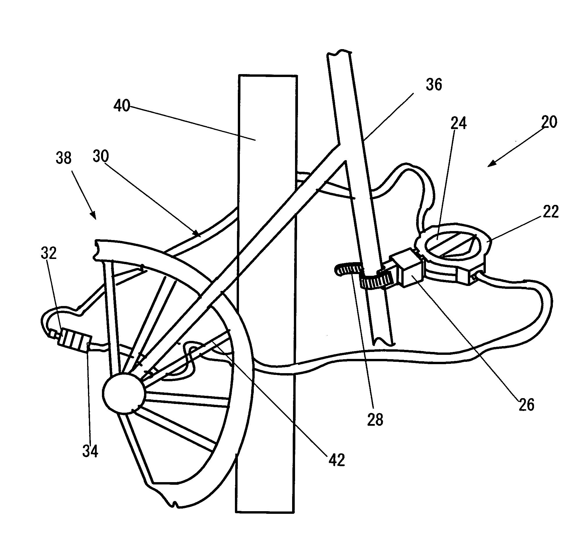
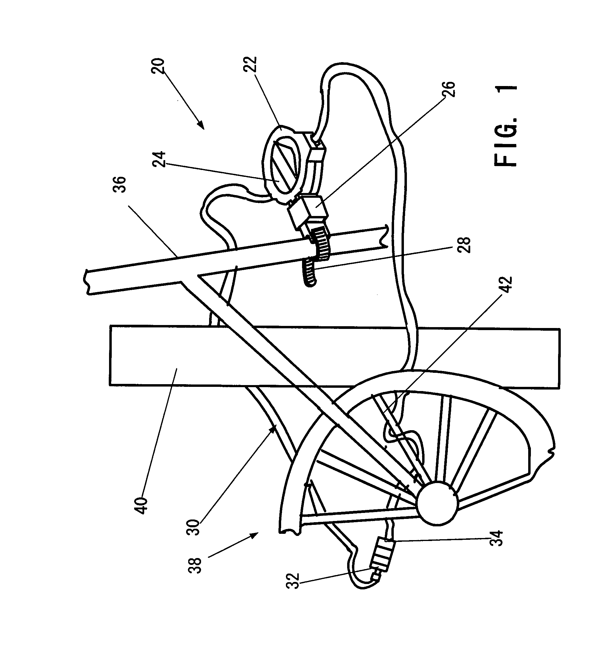
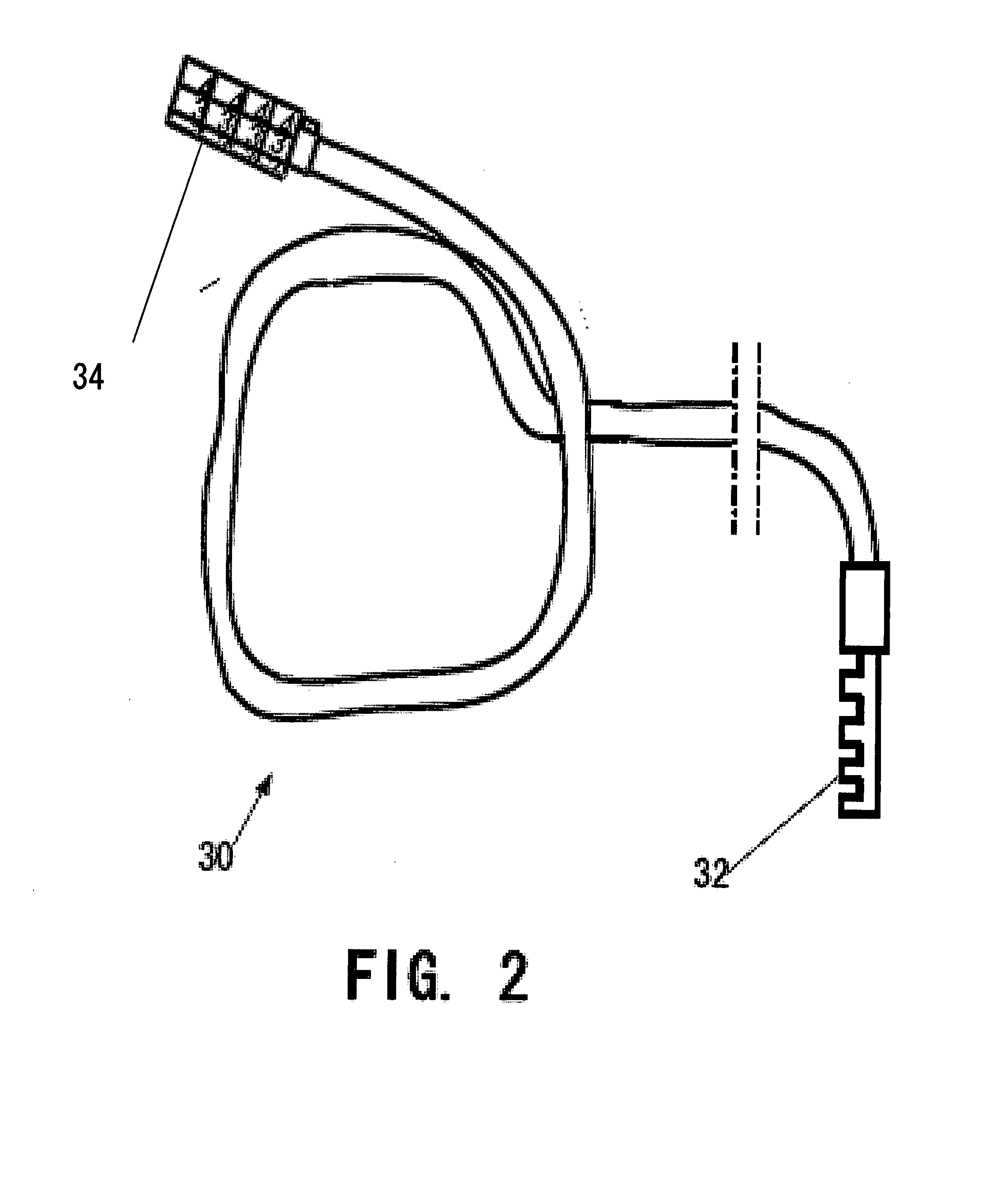
[0028]The anti-theft cable locking device of the invention is particularly suited for securing a bicycle but is not limited only to such application. A general view of the locking device of the invention, which as a whole is designated by reference numeral 20, is shown in FIG. 1 in use for securing a bicycle to a stationary post 40. The locking device 20 consists of a substantially cylindrical housing 22 that has a substantially cylindrical surface and contains a cable rotating drum 24, only the handle portion of which is shown in FIG. 1, a device holder 26 with a securing strap 28, and a wire cable 30 with locking elements 32 and 34 on the cable ends. In FIG. 1 the cable 30 is shown in the form of a loop wound around a frame section 36 of the bicycle 38, the stationary column 40 installed in the street, and is guided around the wheel spike 42. The housing serves not only for retracting the cable but also as a cable storage device.

[0029]Let us now consider the main parts of the lock...


PUM


Abstract

An anti-theft bicycle locking device that consists of a cylindrical housing rotatingly supporting a drum and having a semi-rigid cable which is retracted within a housing by a drum as S-shaped turns formed by a cranking mechanism of the drum consisting of two cylindrical hubs with an opening between them through which the cable is threaded when it is passed through the anti-theft locking device. When the drum is rotated by means of handle portions of the drum exposed through the housing, one exposed end of the cable is retracted onto one side of the drum and the other to the opposite side of the drum. The space between the inner surface of the housing and the outer surface of the drum and the direction of the outlet openings of the housing provide placement of the turns side by side on the drum surface.

Description

BACKGROUND[0001]1. Field of Invention[0002]This invention relates to an anti-theft locking device with a flexible cable, in particular to a bicycle anti-theft locking device with a storage unit for an excess portion of the length of a cable which is not in use.[0003]2. Description of Prior Art[0004]Bicycle theft is a common problem recognized internationally. To overcome these criminal acts, bicycle locks were developed to increase bicycle security. Originally, bicycle locks were heavy, cumbersome, and dangerous to both the bicycle and the consumer. Consequently, bicycle locks evolved to become more compact, efficient, and safe. The bicycle locks on the market today are represented by three basic varieties that involve a cable: 1) a “U-lock”, 2) a straight cable with a lock, and 3) a coiled cable with a lock.[0005]Existing cables with locks are still relatively cumbersome, inconvenient, and potentially dangerous to apply and store. There is a tendency for a coiled cable to spring ba...

Claims


Application Information

Patent Timeline
IPC IPC(8): E05B73/00
CPCE05B67/006E05B37/025Y10T70/409
Inventor BAUMGARTEN, BRET
Owner BAUMGARTEN BRET
Learn More