Combination non-imaging concentrator

Inactive Publication Date: 2009-05-07
SOLFOCUS
View PDF19 Cites 56 Cited by
  • Summary
  • Abstract
  • Description
  • Claims
  • Application Information

AI Technical Summary

Benefits of technology

[0005]The present invention is a combination non-imaging concentrator in which a lens is combined with a light guide. At least one surface or volume is incorporated as an optical element to increase obliquity of reflection at walls of the light guide, thereby increasing the acceptance angle of the combination non-imaging concentrator. The combination non-imaging concentrator may be used in a solar energy s

Problems solved by technology

Thus, the efficiency of a solar concentrator unit is affected not only by the amount of solar energy captured by the unit,

Method used


Image

  • Combination non-imaging concentrator
  • Combination non-imaging concentrator
  • Combination non-imaging concentrator

Examples


Embodiment Construction

[0012]Reference now will be made in detail to embodiments of the disclosed invention, one or more examples of which are illustrated in the accompanying drawings.

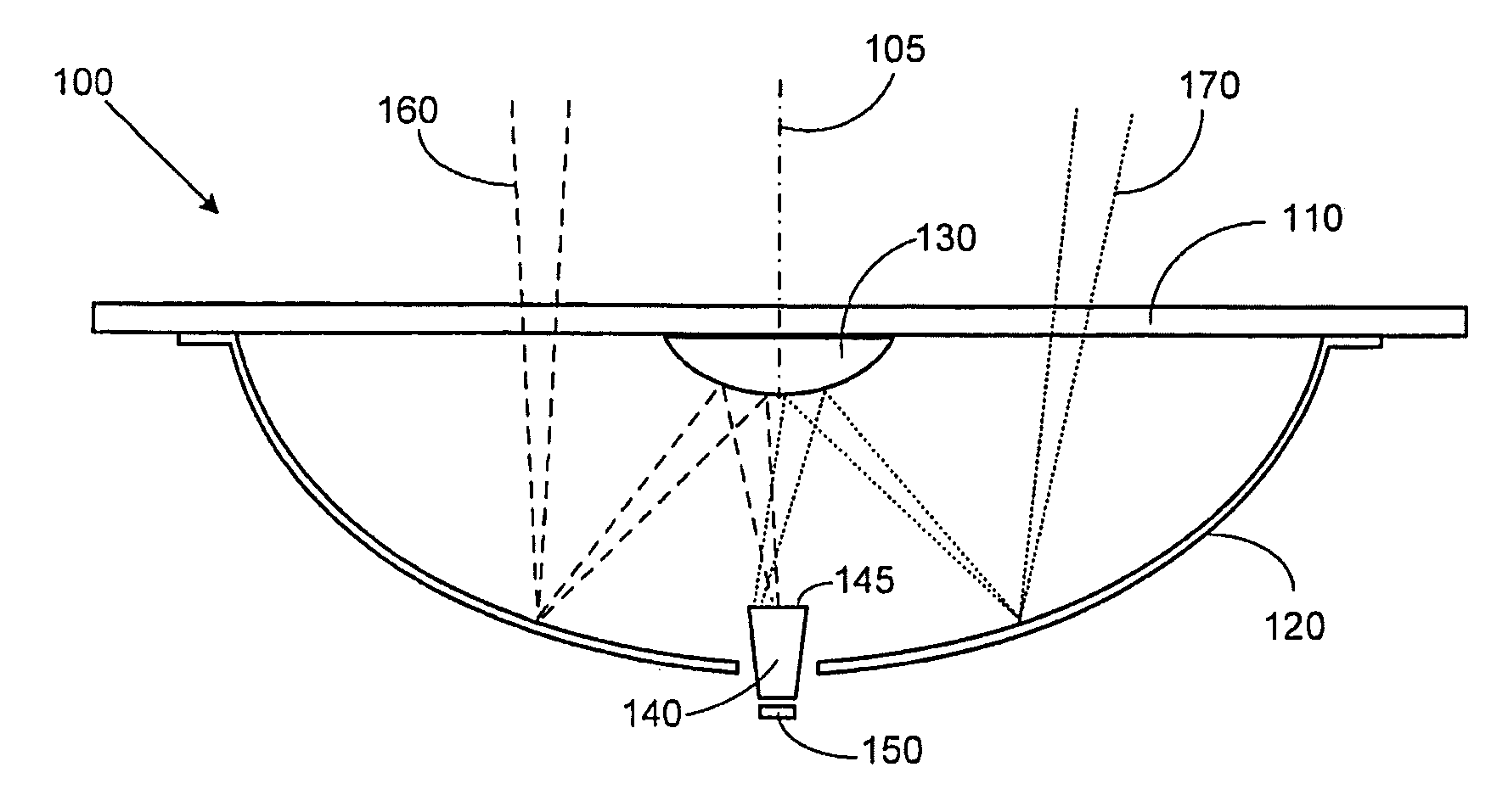
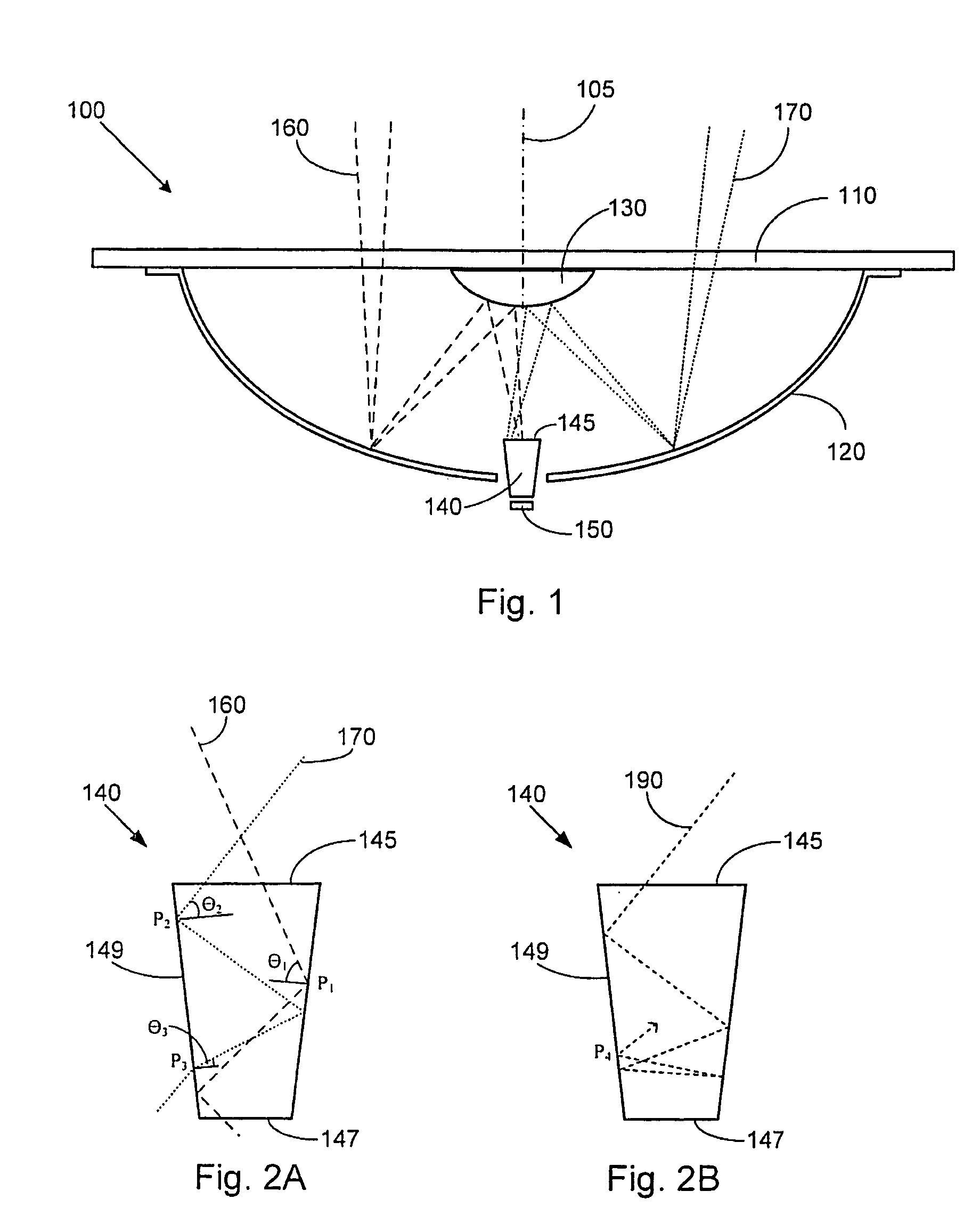
[0013]FIG. 1 depicts a solar concentrator 100 of the type disclosed in U.S. Patent Publication No. 2006 / 0266408, entitled “Concentrator Solar Photovoltaic Array with Compact Tailored Imaging Power Units.” Solar concentrator 100 includes a front panel 110, a primary mirror 120, a secondary mirror 130, a non-imaging concentrator 140, and a solar cell 150. The presence of non-imaging concentrator 140 allows solar cell 150 to be positioned externally to primary mirror 120, where heat sinking measures may be applied. When the sun is aligned with the central axis 105 of solar concentrator 100, solar radiation enters solar concentrator 100 as exemplified by “on-axis” rays 160, illustrated by dashed lines. On-axis rays 160 enter solar concentrator 100 through front panel 110, reflect off of primary mirror 120 and secondary mirror 13...


PUM


Abstract

The present invention is a combination non-imaging concentrator in which at least one surface or volume is incorporated as an optical element to increase obliquity of reflection at walls of a light guide. The combination non-imaging concentrator may be used in a solar energy system to receive solar radiation from optical components and then output the solar radiation to a photovoltaic cell for conversion to electricity. One or more lenses may be formed integrally with the light guide, or may be used in conjunction with the light guide as separate components.

Description

RELATED APPLICATIONS[0001]This application claims priority to U.S. Provisional Patent Application Ser. No. 60 / 985,199 filed on Nov. 3, 2007, entitled “Combination Non-Imaging Concentrator,” which is hereby incorporated by reference as if set forth in full in this application for all purposes.BACKGROUND OF THE INVENTION[0002]Solar power generation involves harvesting solar radiation and converting it to usable energy, such as direct current (DC) electricity. Solar energy may be collected directly onto photovoltaic cells, such as in flat panel technology, or may undergo various stages of refraction and reflection, such as in solar concentrators, before impacting a photovoltaic solar cell. Solar concentrators use vastly decreased amounts of costly photovoltaic material by concentrating incoming solar radiation onto a surface area which is much smaller than that of the entry window area of the overall concentrator unit. Thus, the efficiency of a solar concentrator unit is affected not o...

Claims


Application Information

Patent Timeline
IPC IPC(8): H01L31/04
CPCF24J2/06F24J2/067F24J2/08F24J2/18H01L31/0547Y02E10/44Y02E10/52G02B19/0042G02B19/0028G02B17/086F24S23/00F24S23/79F24S23/12F24S23/30
Inventor JENSEN, JOHN STEFFENMCDONALD, MARK
Owner SOLFOCUS
Why Eureka
Try Eureka