
Frictional engagement device

Inactive Publication Date: 2009-05-07
TOYOTA JIDOSHA KK
View PDF1 Cites 6 Cited by
  • Summary
  • Abstract
  • Description
  • Claims
  • Application Information

AI Technical Summary

Benefits of technology

[0021]The invention provides a small frictional engagement device that is capable of reducing the production cost thereof while making the hydraulic characteristic smooth and reducing the engagement shock by preventing the occurrence of looseness between a bottom plate member and a piston member.

Problems solved by technology

However, according to such a conventional frictional engagement device, due to the looseness that occurs in the direction of the axis between the clutch drum 6 and the pressing ring 12, the pressing ring 12 is drastically moved by the loosened amount when abutting the pressing ring 12 against the outer clutch plate 4 during speed change, causing a drastic change in pressure of the operating oil.
Furthermore, the necessity of disposing the cushion plate 15 between the clutch drum 6 and the pressing ring 12 increases not only the production cost of the frictional engagement device but also the length (entire length) of the axial direction of the frictional engagement device and thus enlarges the frictional device.

Method used


Image

  • Frictional engagement device
  • Frictional engagement device
  • Frictional engagement device

Examples


Embodiment Construction

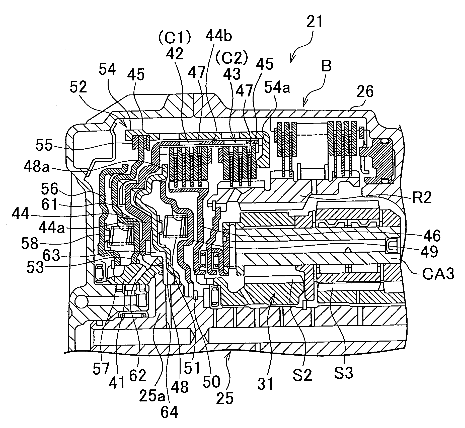
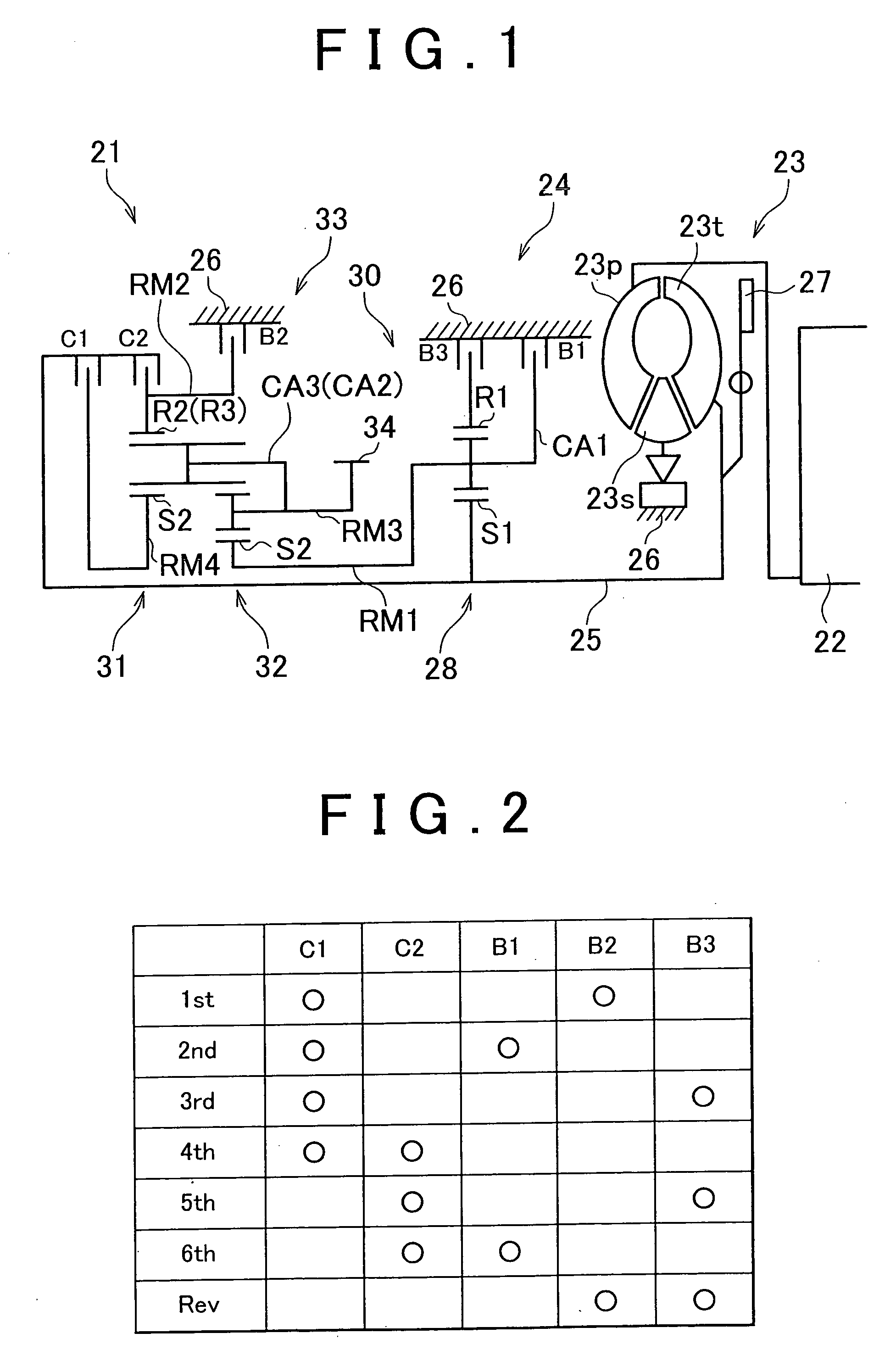
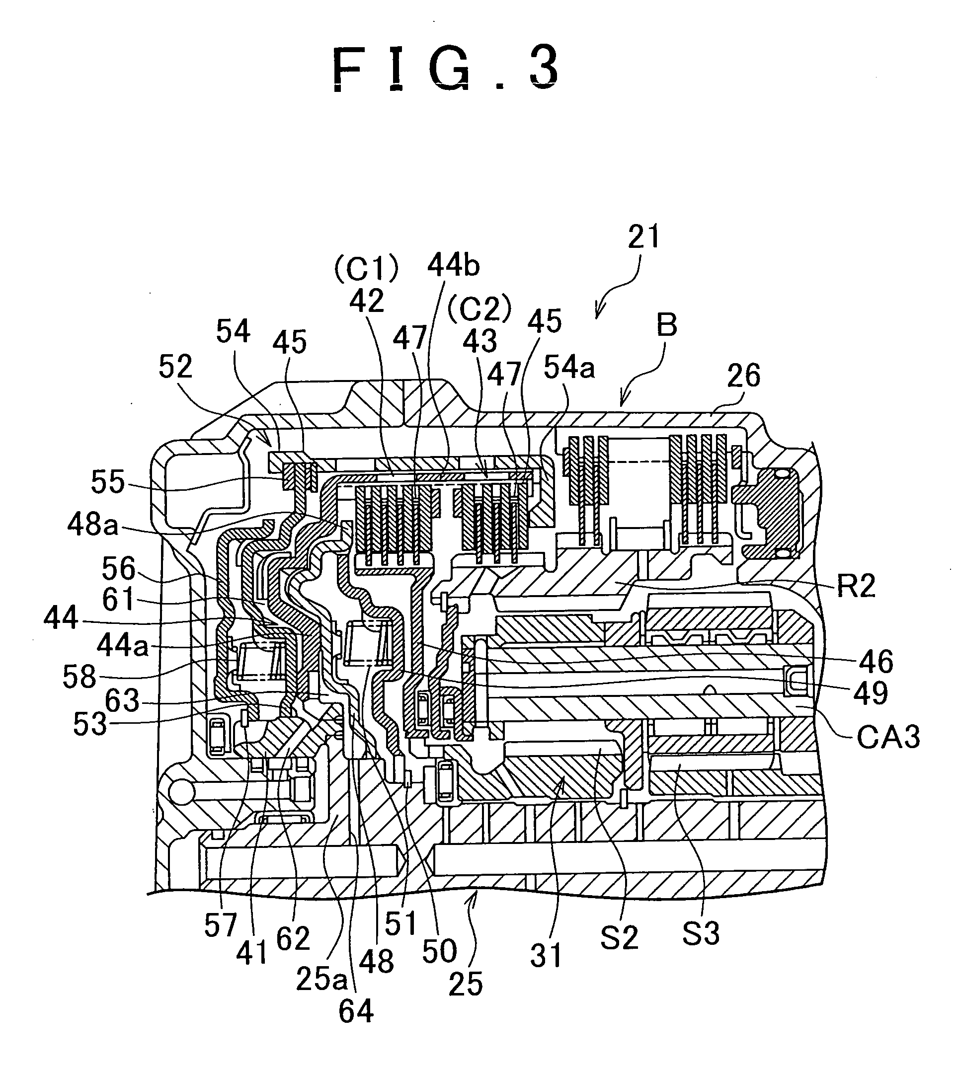
[0041]Hereinafter, an embodiment of the frictional engagement device according to the invention is described with reference to the drawings. FIGS. 1 to 6 are diagrams each showing the embodiment of the frictional engagement device according to the invention, and this embodiment shows an example in which the frictional engagement device is applied to an automatic transmission.

[0042]In FIG. 1, a drive unit 21 for a vehicle, adopted in a front-engine front-drive (FF) vehicle, has an engine 22 as a drive source for travel. An output of the engine 22 configuring an internal combustion engine is transmitted to right and left drive wheels via a torque converter 23 that functions as a fluid type transmission device, an automatic transmission 24, a differential gear unit which is not shown, and a pair of axles.

[0043]The torque converter 23 has a pump impeller 23p coupled to a crankshaft of the engine 22, a turbine impeller 23t coupled to an input shaft 25 of the automatic transmission 24, an...


PUM


Abstract

A wave washer is interposed on an inner peripheral groove via a snap ring. The wave washer urges a radiation direction outer end of a bottom plate member against a wall surface side of the inner peripheral groove in a direction of an axis.

Description

INCORPORATION BY REFERENCE[0001]The disclosure of Japanese Patent Application No. 2007-289776 filed on Nov. 7, 2007 including the specification, drawings and abstract is incorporated herein by reference in its entirety.BACKGROUND OF THE INVENTION[0002]1. Field of the Invention[0003]The invention relates to a frictional engagement device. More particularly, the invention relates to a frictional engagement device that is provided in an automatic transmission or the like and has an engaging / releasing part for establishing and releasing engagement among a plurality of friction plates.[0004]2. Description of the Related Art[0005]A general automatic transmission that is mounted in an automobile or other vehicle has a frictional engagement device for changing a power transmission passage of the automatic transmission. Such a frictional engagement device establishes and releases engagement between a clutch and brake by establishing and releasing engagement among a plurality of friction plat...

Claims


Application Information

Patent Timeline
IPC IPC(8): F16D13/56
CPCF16D13/70F16D2048/0212F16D25/12F16D25/0638
Inventor GOTO, SHINTAROHARASHIMA, TERASUKATO, NAOKI
Owner TOYOTA JIDOSHA KK
Learn More