Electrode contact pellet and associated photoionisation detector assembly

a technology of photoionisation detector and electrode contact, which is applied in the direction of rotary current collector, coupling device connection, non-rotary current collector, etc., can solve the problem of poor proportionality between response and ionisable gas concentration, the response to organic gas not to increase in proportion, and the problem of generating such a voltage becomes more problematic. , to achieve the effect of low cost and easy replacemen

Active Publication Date: 2009-05-07
ION SCI
View PDF12 Cites 6 Cited by
  • Summary
  • Abstract
  • Description
  • Claims
  • Application Information

AI Technical Summary

Benefits of technology

[0023]It is an object of the present invention to provide a pellet, and an associated method of its assembly, for use as an electrode contact assembly in a PID which overcomes, or at least substantially reduces, the disadvantages discussed above in relation to the prior art arrangements. For example, the pellet can be low cost and therefore readily replaceable.SUMMARY OF THE INVENTION
[0025]Advantageously, the closure member(s) are protrusions from the closure but other means, such as the shape of the closure, can readily be employed for engaging the electrode contact(s) and thereby changing the plane thereof when the pellet is in an assembled condition.
[0027]The pellet base may be provided in one wall thereof with a plurality of holes corresponding to the number of electrode contacts, so that, in the assembled condition of the pellet, the contacts overlie respective ones of those holes through which fixed terminal pins, preferably of the same height, can be received to engage respective ones of the contacts, to provide ohmic contacts therebetween. As the fixed terminal pins are received through the base holes, they may deform the contacts in scraping engagement therewith, to enhance such ohmic contacts. In this embodiment, the free ends of the contacts, which are spaced from the closure members engaging them, are deformed in a direction which is generally opposite to that in which the contacts are deformed initially when the closure is fitted to the base.

Problems solved by technology

Second, the absorption of light by ionisable gases increases with distance from the lamp, causing the response to an organic gas not to increase in proportion to its concentration, even at quite modest concentrations (tens of parts per million of ionisable gas) in chambers having an electrode gap of more than a few millimetres.
Generating such a voltage becomes more problematic as the gap across the electrodes is increased.
Finally, positive and negative ions are more likely to encounter each other and recombine as the electrode gap is increased, again causing poor proportionality between response and ionisable gas concentration.
Further, collisions between such negative ions and neutral molecules within the ionisation chamber can generate ion clusters which, being of high molecular weight, are very prone to deposition on surfaces, such as the lamp window.
Sometimes, a photoionisation chamber may also be fouled by liquids being drawn into it.
It will be apparent that photoionisation chambers are frequently of small dimensions and, in certain applications, prone to contamination or mechanical damage during use and servicing.
However, there has frequently been difficulty in assuring good electrical contact between the electrode terminals in the replaceable chamber and terminals from supporting electronic circuitry contained within a sensing member which accommodates the replaceable ionisation chamber.
In particular, spring-loaded retractable pins, which ensure a force is applied between the contacts, do not always retain their spring loading.
Also, pins inserted into metal or metal-coated holes are prone to failure after multiple engagement and removal of the ionisation chamber.
This technique requires much space and if specialised miniature telescopic pins are used, then the costs may be prohibitive.
There are several technical problems with this approach.
First, the expensive telescopic pins are, for practical reasons, located within the retained PCB exterior to the disposable pellet.
The whole assembly can be used in aggressive and potentially corrosive atmospheres and thus, after some repeated use, the pins may become damaged or corroded, thereby losing their effectiveness in communicating electrical signals between the pellet and the externally retained PCB.
A further problem with this prior art arrangement is at the points of contact between the pins and contacts.
These points of contact are generally between the pins and contacts which are perpendicular to each other and, thus, have no means for wiping the points of contact clean whilst making contact between the pins and contacts.
Oxide or external debris if not wiped away during the contact-making generation may impair good ohmic contact for electrical signals.
However, this particular prior art arrangement does have some disadvantages.
The main disadvantage is that the socket and pins must be parallel to each other and to the direction of their relative travel.
Clearly, this is not too much of a problem if it is just one or two pins, as in the prior art example, but when, say, five pins are used then this becomes more difficult to achieve.
Further, this option still tends to be unduly expensive in relation to unit costs and assembly requirements.

Method used


Image

  • Electrode contact pellet and associated photoionisation detector assembly
  • Electrode contact pellet and associated photoionisation detector assembly
  • Electrode contact pellet and associated photoionisation detector assembly

Examples


Embodiment Construction

[0046]All references to downward and other directions are relative to the base of the pellet, as shown in the drawings, and do not imply any particular orientation of the pellet.

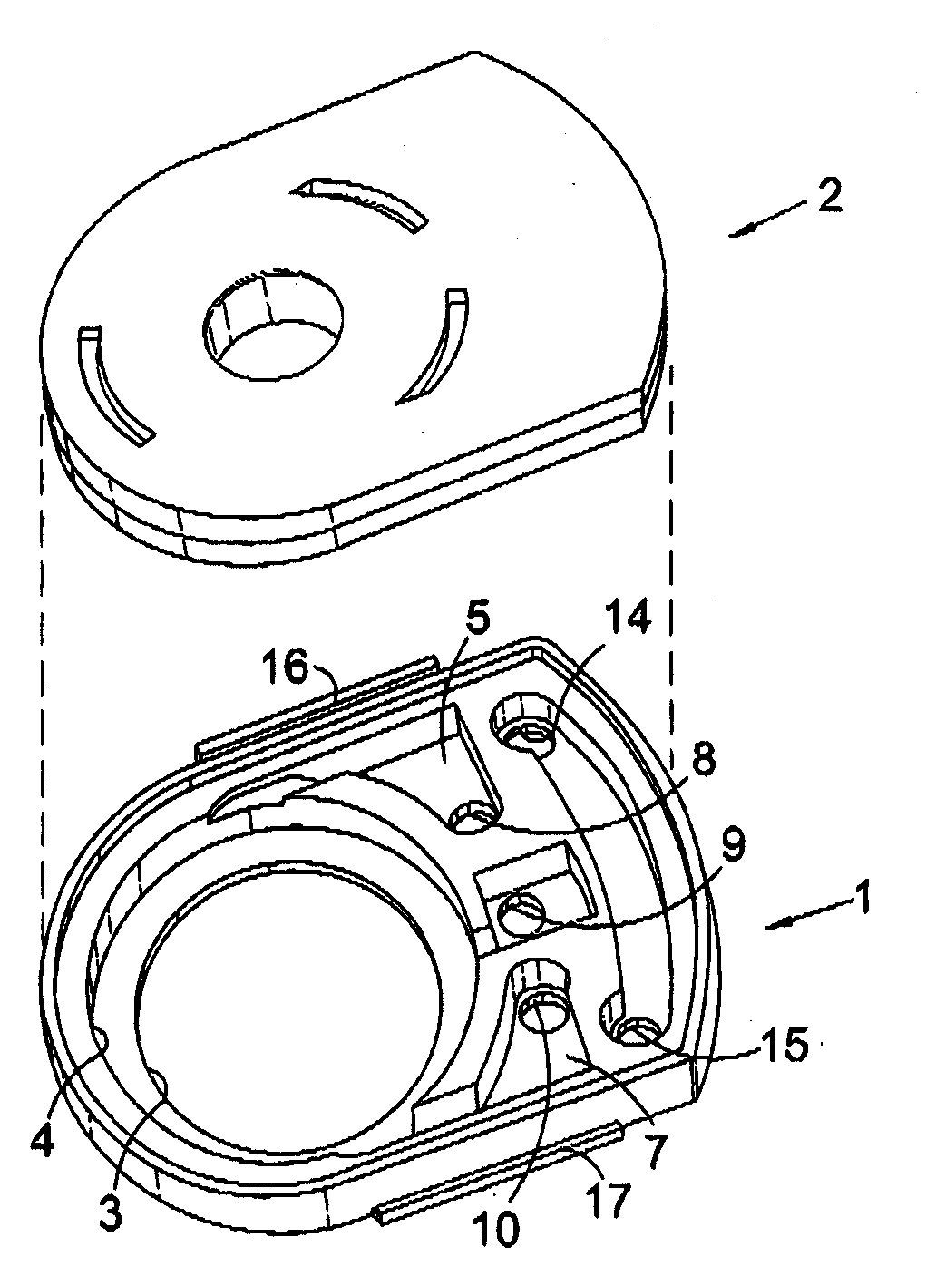
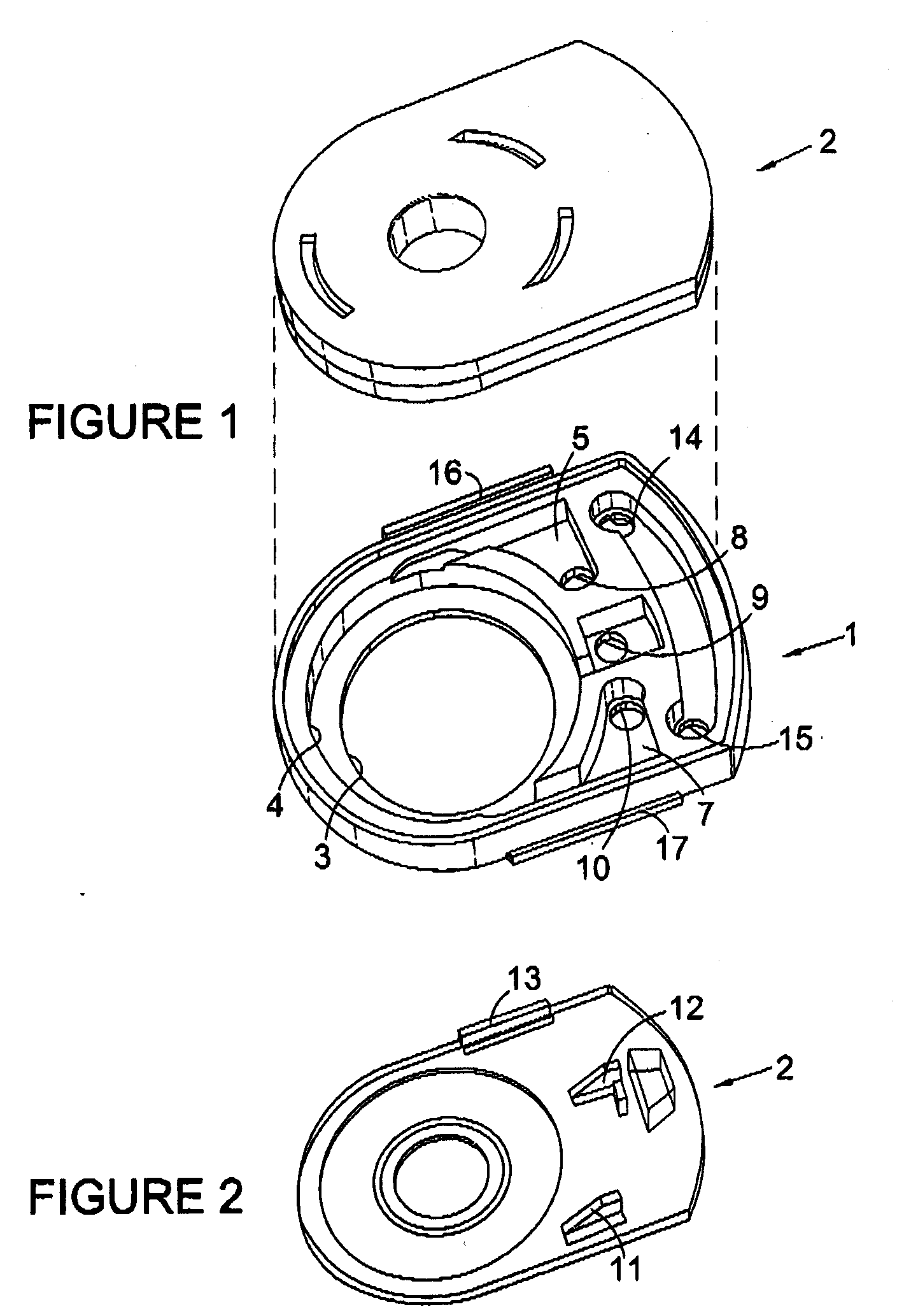
[0047]Referring first to FIG. 1 of the accompanying drawings, an electrode pellet in accordance with the invention, and for use with a photoionisation detector (PID) capsule, comprises a moulded plastics base body, generally designated 1, and a moulded plastics lid, generally designated 2, which can be fitted and secured to the pellet base body 1.

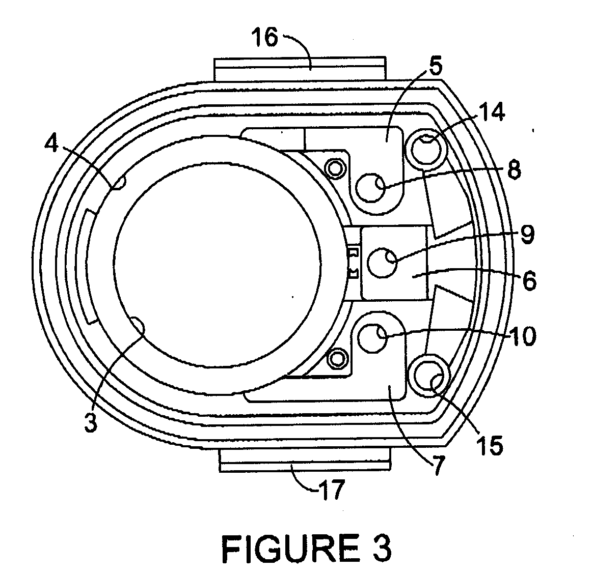
[0048]The base body 1 comprises a circular aperture 3 for alignment with one end of an ionisation lamp of a PID capsule, as will be described hereinbelow.

[0049]A circular recess 4 concentric with the aperture 3 is arranged to receive therein three electrodes (not shown) separated by respective electrically-insulating spacers (also not shown), as will also be described hereinbelow.

[0050]Each electrode has a contact (not shown) which extends into a respective one of t...


PUM


Abstract

A demountable pellet is disclosed for use as an electrode contact assembly. The pellet comprises a base 1 upon which is mounted a plurality of electrodes 18, 19, 20 arranged in respective spaced parallel planes and having respective contacts 23, 24, 25 protruding from them. A closure 2 for the base 1 has a member 11, 12, 13 engaging at least one of the electrode contacts. In an unassembled condition of the pellet, with the closure 2 separate from the base 1 and each closure member disengaged from its respective electrode contact, the contacts 23, 24, 25 lie in respective spaced parallel planes. In the assembled condition of the pellet with each closure member engaging its respective electrode contact, at least one of the contacts 23, 24, 25 lies in a plane other than that in which it lay in the unassembled condition of the pellet.

Description

FIELD OF THE INVENTION[0001]This invention relates to a demountable electrode contact assembly. Such self-contained sub-assemblies are conveniently referred to as “pellets”. The present invention is particularly suitable for use in a photoionisation detector (PID) which enables gases, particularly air, to be sampled for gases which form ions when exposed to light emitted from a UV light source within the PID. These photoionisable gases can be harmful or dangerous to health, can present a fire risk, and / or can indicate the failure of equipment designed to contain them in a gaseous or liquid state.BACKGROUND OF THE INVENTION[0002]PIDs usually incorporate a chamber through which a sample gas is passed by means of suitable tubing, pumps, fans and the like. The chamber is exposed to photons. A proportion of the photons has sufficient energy to disassociate any photoionisable gas molecules within the sample into ions. This process is known as photoionisation and the chamber itself is desc...

Claims


Application Information

Patent Timeline
IPC IPC(8): G01N27/62
CPCG01N27/66H01J1/88H01J1/92H01J1/94H01R13/40H01R13/4361H01R13/514
Inventor STOCKDALE, MARK JULIANEAGLING, KARA MICHELE
Owner ION SCI
Why Eureka
Try Eureka