Acoustic Emission Measuring Device, Power Transmission Device, and Rolling Bearing Device

a technology of acoustic emission and measuring device, which is applied in the direction of instruments, slip couplings, and gearing, etc., can solve the problems of increasing operating costs, inability to use apparatus, and inability to capture effective ae signals by ae sensors, etc., and achieves low operation costs, low operation costs, and correct detection ae signals

Inactive Publication Date: 2009-05-07
JTEKT CORP +1
View PDF0 Cites 9 Cited by
  • Summary
  • Abstract
  • Description
  • Claims
  • Application Information

AI Technical Summary

Benefits of technology

[0006]It is therefore an object of the present invention to provide a compact AE measuring device which does not require any power supply on the transmitting side of the AE measuring device to achieve a low operation cost and which is able to correctly detect AE signals. It is another object of the present invention to provide a compact power transmission device which does not require any power supply on the transmitting side of the power transmission device to achieve a low operation cost and which is able to correctly detect AE signals from a power transmission member which is a rotary part. It is a further object of the present invention to provide a compact rolling bearing device which does not require any power supply on the transmitting side of the rolling bearing device to achieve a low operation cost and which is able to correctly detect AE signals from a rotating wheel.

Problems solved by technology

However, the conventional apparatus with an AE sensor has a problem that the transmitting side of the apparatus needs a power supply for amplifying an AE signal, thereby increasing the operating cost.
The conventional apparatus also has a problem that since AE signals are transmitted using a transmitting antenna, the transmitting side of the apparatus needs a large space for mounting the transmitting antenna, and if the mounting space of the transmitting side of the apparatus is small, the apparatus could not be used.
However, the conventional apparatus now has a problem that the AE signals become feeble so that effective AE signals cannot be thus captured by the AE sensor.
Thus, it cannot be correctly determined whether the rotary part is abnormal or not.

Method used


Image

  • Acoustic Emission Measuring Device, Power Transmission Device, and Rolling Bearing Device
  • Acoustic Emission Measuring Device, Power Transmission Device, and Rolling Bearing Device
  • Acoustic Emission Measuring Device, Power Transmission Device, and Rolling Bearing Device

Examples


first embodiment

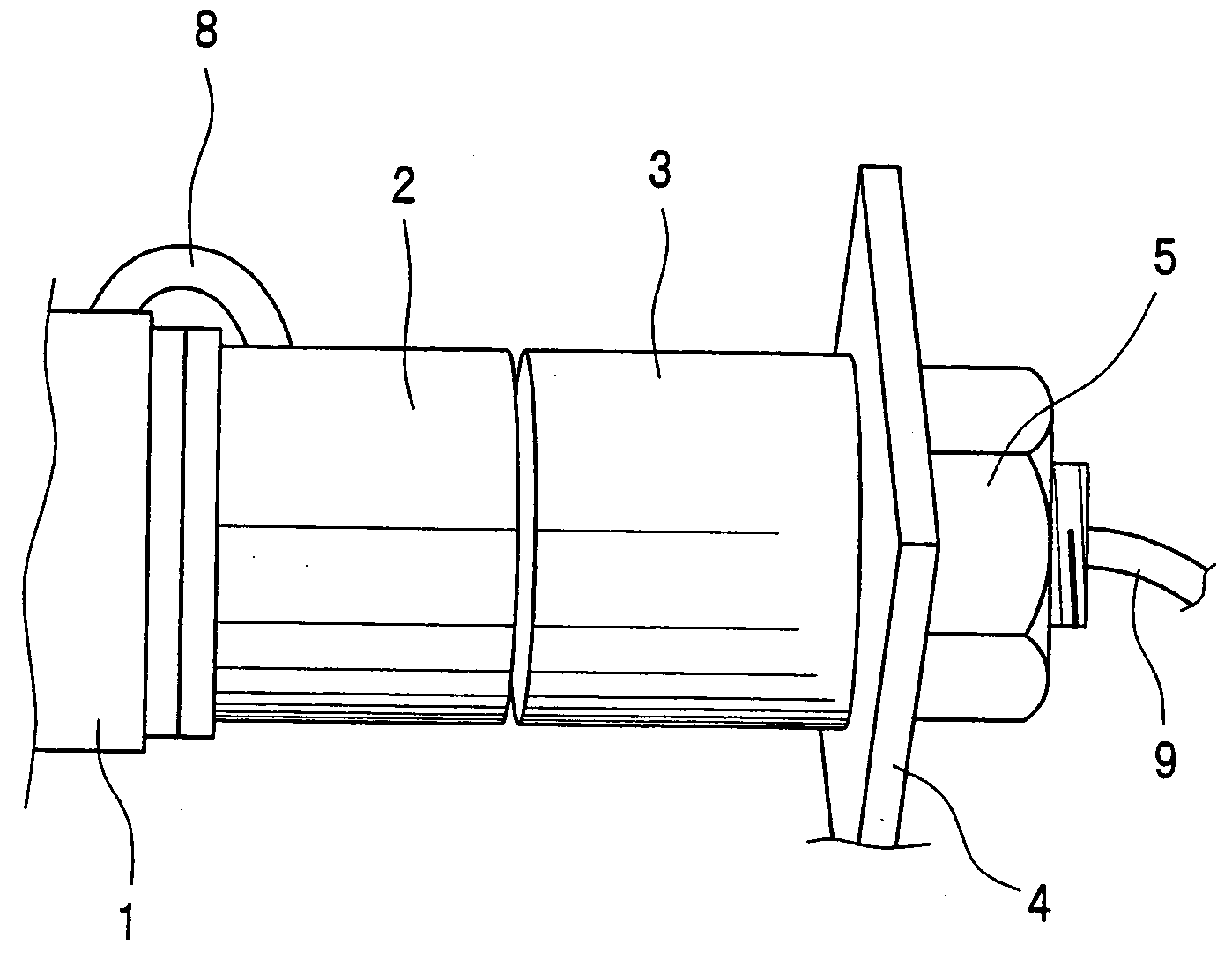
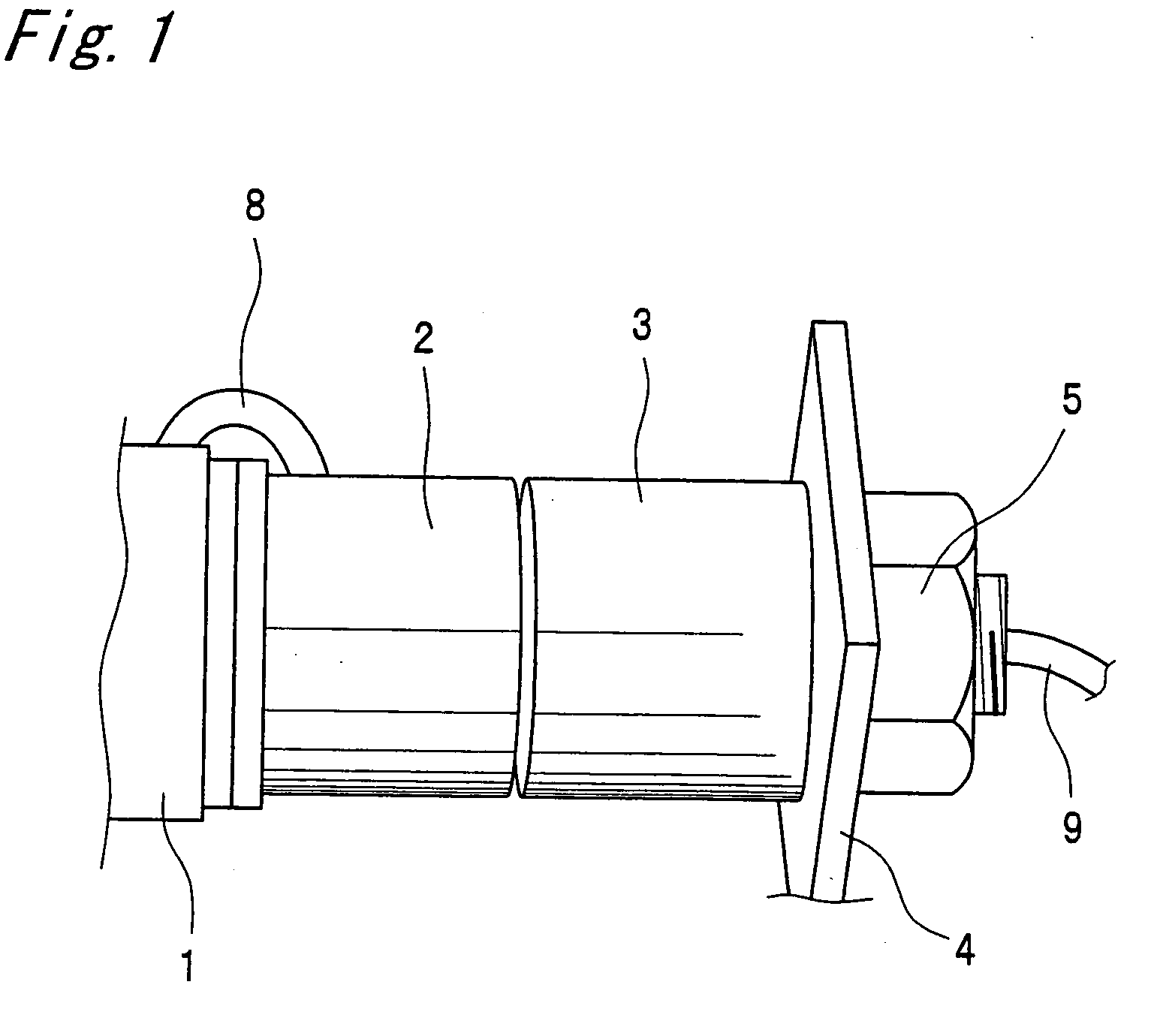
[0069]FIG. 1 shows the appearance of part of an acoustic emission (AE) measuring device which is the present invention.

[0070]The AE measuring device includes a first coil case 2 and a second coil case 3. The first coil case 2 is shaped almost like a cylinder. The first coil case 2 is fixed to one axial end face of the rotating shaft 1 and rotates in synchronization with the rotating shaft 1. The second coil case 3 has about the same shape as the first coil case 2. The second coil case 3 is adjacent to the first coil case 2 via a small clearance in the axial direction of the first coil case 2. The second coil case 3 is fastened to a clamp member 4 fixed to a housing accommodating the rotating shaft 1 with a nut 5 so that the second coil case 3 is stationary relative to the housing.

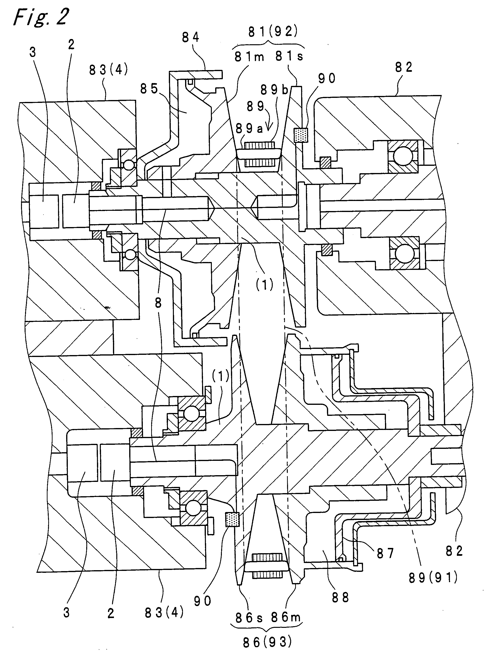
[0071]The AE measuring device has a piezoelectric element (not shown) as an example of an AE sensor. The piezoelectric element is embedded in the back of a stationary pulley half body 81s, 86s as described ...


PUM

PropertyMeasurementUnit
frequenciesaaaaaaaaaa
frequencyaaaaaaaaaa

Abstract

An acoustic emission measuring device in which a piezoelectric element (63) used as an AE sensor is secured to the inner ring (62) of a ball bearing (61) fixedly fitted onto a rotating shaft (60). The axial end face of a roughly tire-shaped case (65), which is capable of rotating in synchronism with the inner ring (62) and storing a first coil in which a current flows from the piezoelectric element (63), is secured to the inner ring (62). The axial end face of a roughly tire-shaped case (66) for storing a second coil is secured to an outer ring (64). The first coil and the second coil are oppositely disposed radially outside of the rotating shaft (60) so that the first coil and the second coil can face each other in the radial direction.

Description

BACKGROUND OF THE INVENTION[0001]The present invention relates to an acoustic emission (AE) measuring device. The present invention also relates to a power transmission device having a power transmission member and an AE sensor. The present invention also relates to a rolling bearing device having a rolling bearing and an AE sensor.[0002]A conventional apparatus with AE sensor that is provided with an AE measuring device is described in JP 9-26414 A.[0003]In this apparatus with an AE sensor, an AE signal from the AE sensor mounted on a rotary part is frequency-modulated by a frequency modulation circuit, and the modulated AE signal is amplified. The amplified AE signal is then transmitted and received by radio via a transmitting antenna and a receiving antenna. The AE signal received by the receiving antenna is input to an AE analyzer via an amplifier, a frequency-modulation receiving circuit, and a frequency demodulation circuit to diagnose an abnormality of the rotary part by the ...

Claims


Application Information

Patent Timeline
Patent Type & Authority Applications(United States)
IPC IPC(8): F16C41/00G01N29/14G01H11/00
CPCF16C19/52F16C33/58F16H9/18G01M13/028Y10T464/20G01N29/14G01N29/223G01N2291/101G01N2291/2696G01M13/045F16D2300/18
Inventor OGUMA, NORIYASUMURAKAMI, ISAO
Owner JTEKT CORP
Why Eureka
Try Eureka