
Composite cover

a technology of composite covers and covers, applied in the field of composite covers, can solve the problems of unstable circuits, oscillations, and the ability of unintentional radiating energy from the inside of the cover, and achieve the effects of reducing weight, reducing costs, and reducing conductivity

Inactive Publication Date: 2009-05-07
HONEYWELL INT INC
View PDF7 Cites 100 Cited by
  • Summary
  • Abstract
  • Description
  • Claims
  • Application Information

AI Technical Summary

Benefits of technology

[0005]The present invention provides a circuit board cover that provides dust, dirt and incidental moisture protection over an extended temperature range, EMI shielding to prevent radiation of internal circuit energy outside of the cover and prevents the entrance of external EMI. Also, the cover has mechanical strength for protection of circuitry and transfers heat created by internal circuitry. The present invention has lower cost and weight than typical machined metal covers, lower levels of radiated emissions and improved resistance to incident external radiation. The present invention may provide both electric and magnetic shielding.
[0006]In one aspect of the invention, the cover is made of a “low Q” lossy material that provides shielding and performs repeated absorption of reflected energy. Any energy that initially passes through the lossy cover is reflected back to the cover and is absorbed or dissipated at each subsequent reflection. The lossy cover effectively dissipates energy reaching its surface, thereby reducing cavity resonance and re-radiation from slot gaps.
[0008]Injection molded composite covers with modest conductivity also offer the benefits of reduced weight and significantly reduced costs over machined metal covers and very high conductivity composite covers.

Problems solved by technology

However, each metal cover also internally creates one or more resonant cavities with relatively high Q (ratio of power stored to power dissipated) that are capable of supporting undesired transmission modes and / or causing circuits to become unstable and oscillate.
Furthermore, any metal cover that is installed is capable of unintentionally radiating energy from within the cover if any unintended gaps between the cover and the circuit board ground are allowed to exist.
When these circuit assemblies or modules with metal covers are then placed within a metal chassis, unintended radiation from covers on circuit boards and interconnect wiring establishes zones of strong electromagnetic fields that may interfere with other modules or radiate from the metal chassis at a gap or slot in the cover.

Method used


Image

  • Composite cover
  • Composite cover
  • Composite cover

Examples


Embodiment Construction

[0016]An (avionics) circuit board cover in one embodiment includes a plastic resin material capable of retaining full strength over expected operating and storage temperature ranges. The cover includes a polymeric resin combined with composite fill material(s) that in one embodiment meet Federal Aviation Administration (FAA) Flammability, Smoke Density and Toxicity (FST) requirements for commercial aircraft applications. For internally packaged circuit boards, the resistivity of the composite material is preferably less than 10 ohm-cm and greater than 0.5 ohm-cm.

[0017]Electromagnetic simulation and measurement results have shown that increasing conductivity is not desired for applications of covers on circuitry that is contained within other packaging enclosures.

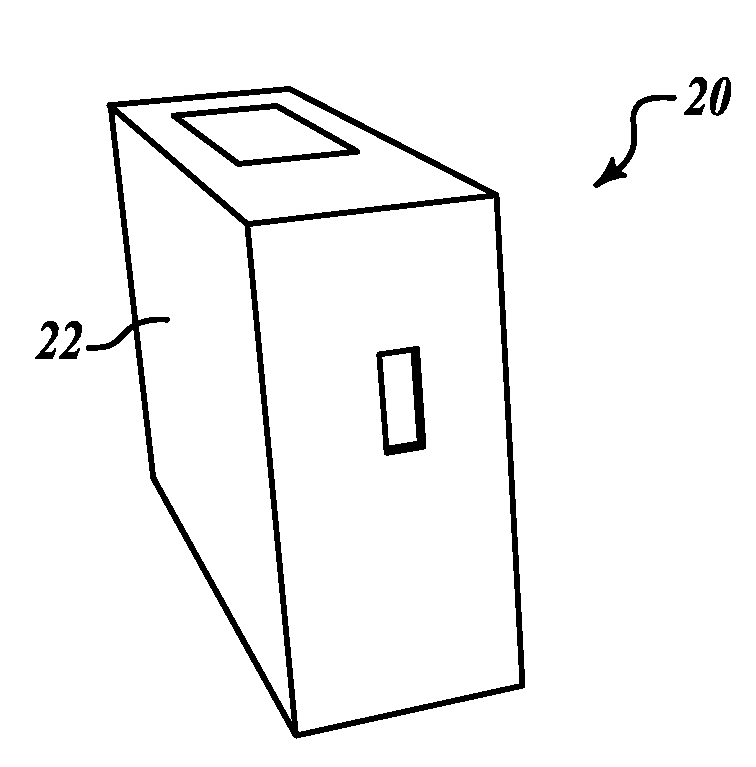
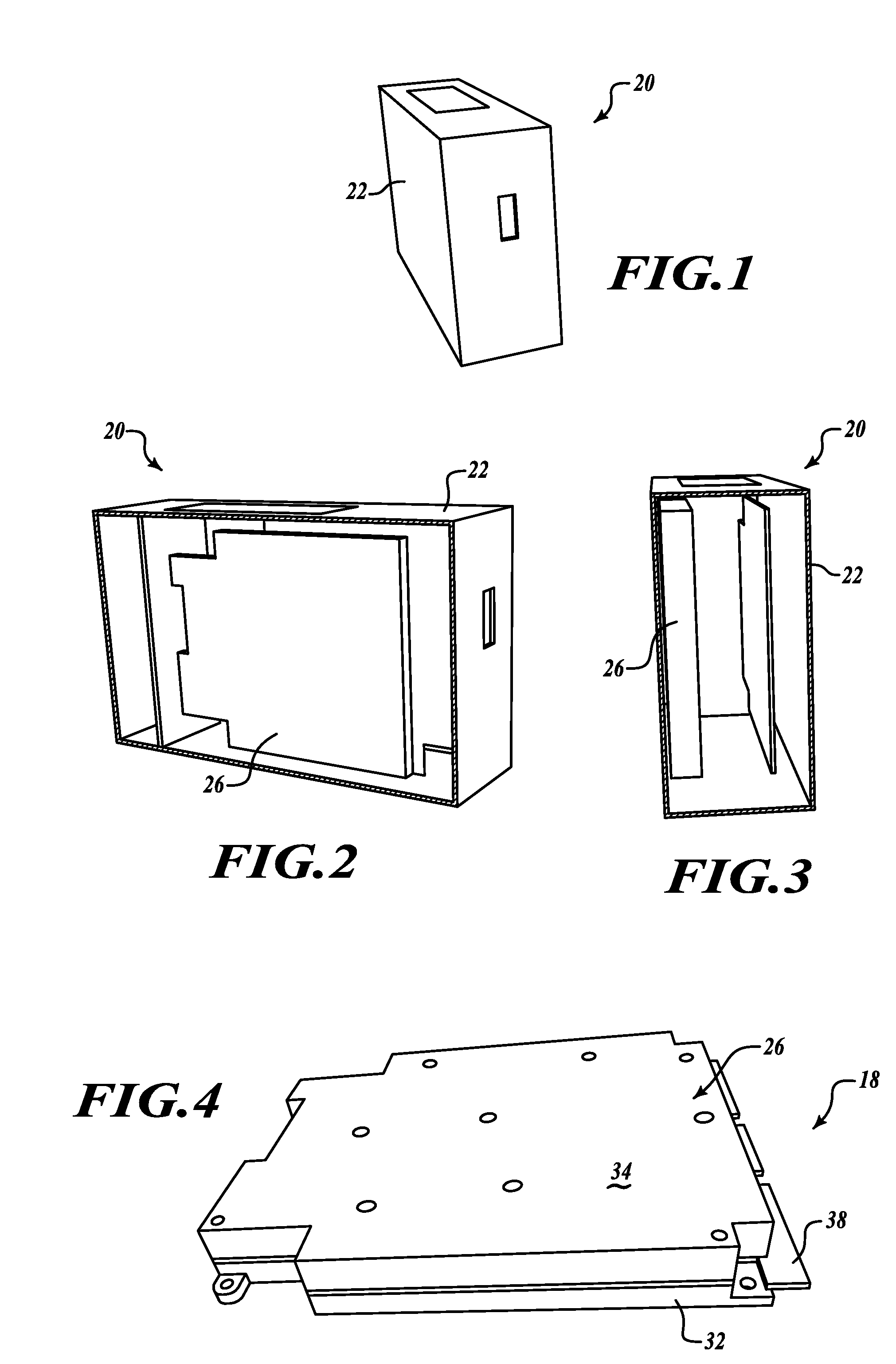
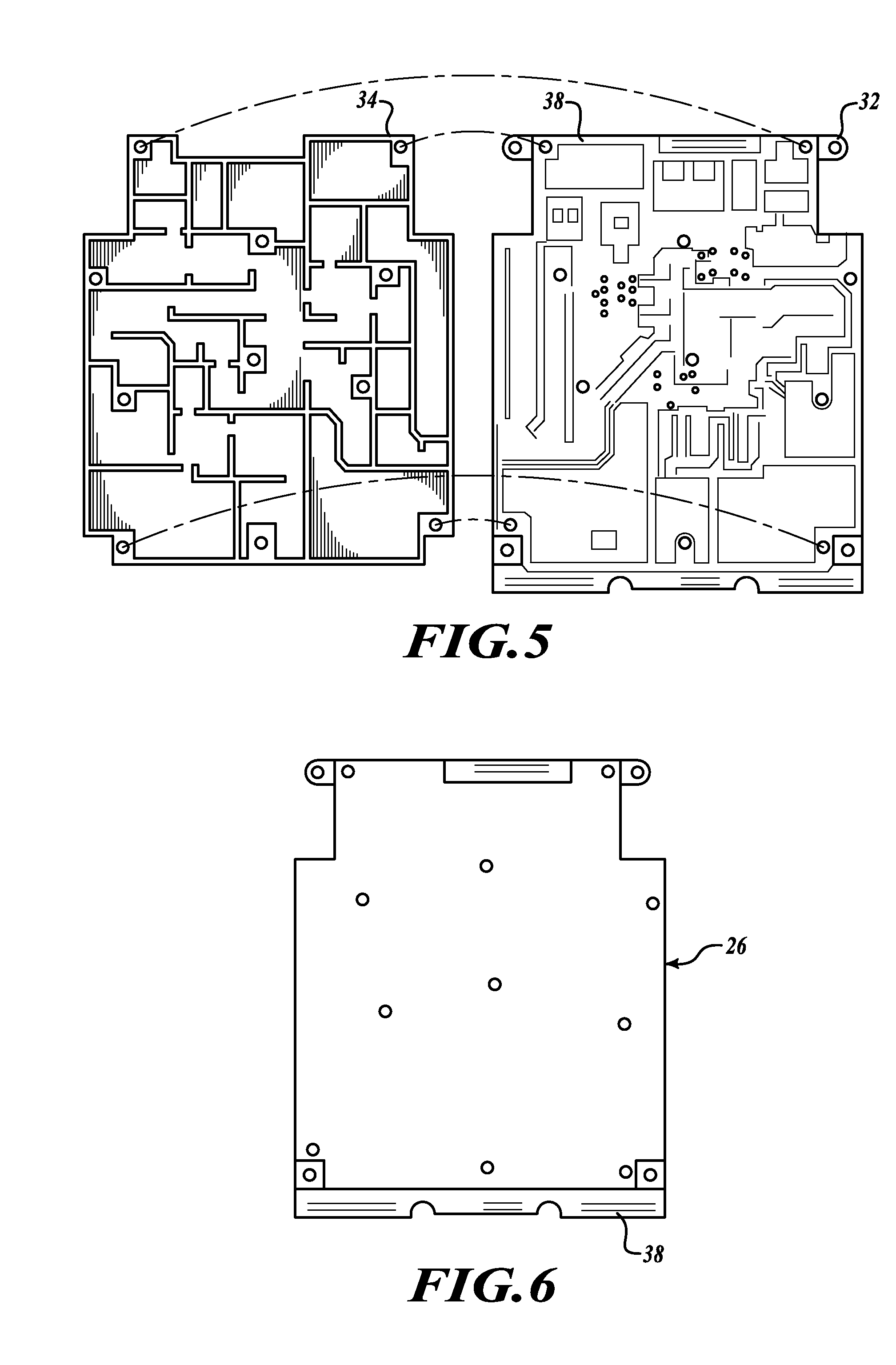
[0018]FIGS. 1-3 illustrate various perspective views of an electronics box 20 that is used to house one or more circuit boards. In one embodiment of the present invention, one or more of the circuit boards is located within ...


PUM

PropertyMeasurementUnit
temperaturesaaaaaaaaaa
densityaaaaaaaaaa
elongationaaaaaaaaaa

Abstract

A composite cover for dust, dirt and incidental moisture protection over an extended temperature range, EMI shielding to prevent radiation of internal circuit energy and preventing the entrance of external EMI. Also the cover provides mechanical strength and protection of circuitry and radiates heat created by internal circuitry. The cover provides lower levels of radiated emissions and improved resistance to incident external radiation. Electric and magnetic shielding is also provided.

Description

PRIORITY CLAIM[0001]This application claims the benefit of U.S. Provisional Application Ser. No. 60 / 986,199 filed Nov. 7, 2007, the contents of which are hereby incorporated by reference.BACKGROUND OF THE INVENTION[0002]Traditionally electromagnetic covers are made from multiple forms of aluminum that are attached to circuit boards that contain RF, microwave, millimeterwave, or high speed digital circuitry to prevent radiation into adjacent boards or modules and from radiating outside of the overall chassis.[0003]Metal covers generally succeed very well in achieving high shielding effectiveness. However, each metal cover also internally creates one or more resonant cavities with relatively high Q (ratio of power stored to power dissipated) that are capable of supporting undesired transmission modes and / or causing circuits to become unstable and oscillate. Cavities with high Q easily store energy at a resonant frequency. Cavities with low Q dissipate resonant energy and suppress osci...

Claims


Application Information

Patent Timeline
Patent Type & Authority Applications(United States)
IPC IPC(8): B32B9/00
CPCY10T428/30B32B27/00
Inventor VACANTI, DAVID C.STEVENSON, JAMES
Owner HONEYWELL INT INC
Learn More