Device for Attaching a Label to a Substrate

a technology for attaching devices and substrates, which is applied in the direction of lamination control, transportation and packaging, other domestic objects, etc. it can solve the problems of psa losing its ability to bind the label to the object, the process can last for hours, and the use of harsh environments is limited. , to achieve the effect of small cross-section and longer length

Inactive Publication Date: 2009-05-07
BRADY WORLDWIDE INC
View PDF6 Cites 9 Cited by
  • Summary
  • Abstract
  • Description
  • Claims
  • Application Information

AI Technical Summary

Problems solved by technology

For example, their use in harsh environments is of limited value.
Under conditions of high heat (or extreme cold), elevated or reduced pressure and / or exposure to various solvents, particularly over extended periods of time, the PSA can lose its ability to bind the label to the object.
These processes can last for hours and can include exposure to heat and vacuum.
Notwithstanding the wide range of PSAs available, e.g., acrylates, tackified natural and synthetic rubbers, silicones and urethanes, none have shown resistance to the complete range of conditions to which a tissue cassette is typically exposed.
As such, PSAs are generally unsuitable for reliable attachment of identification labels to tissue cassettes and, for that matter, to many consumer and industrial process containers that are also exposed to harsh environmental conditions, such as those used in the food and dairy industries, or those used for storage of hazardous materials, or those used in subzero storage (where many PSAs lose their adhesive properties).
Moreover, PSAs can provide inadequate adhesion in those situations where the substrate is not exposed to harsh environmental conditions, but where the surface of the substrate is too rough or textured to allow for good adhesion between it and the label.
For example, the use of staples, pins and other mechanical fasteners is common, although problematic, because the fasteners interfere with the handling of the cassette.
Moreover, the design and construction of the label and substrate often do not lend themselves for use with mechanical fasteners.

Method used


Image

  • Device for Attaching a Label to a Substrate
  • Device for Attaching a Label to a Substrate
  • Device for Attaching a Label to a Substrate

Examples


Embodiment Construction

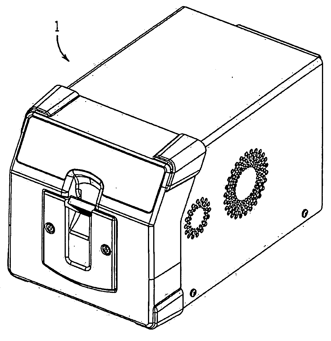
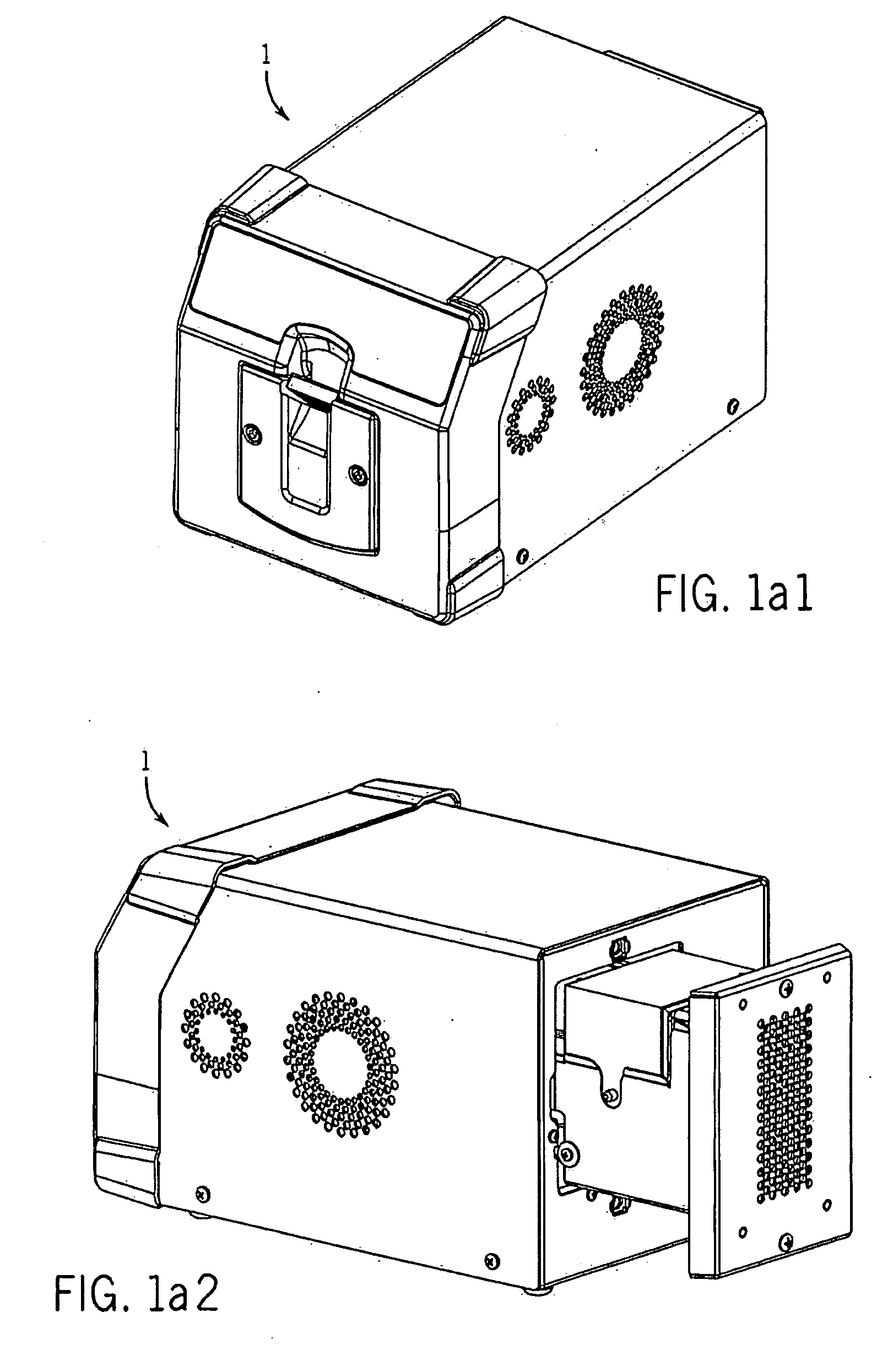
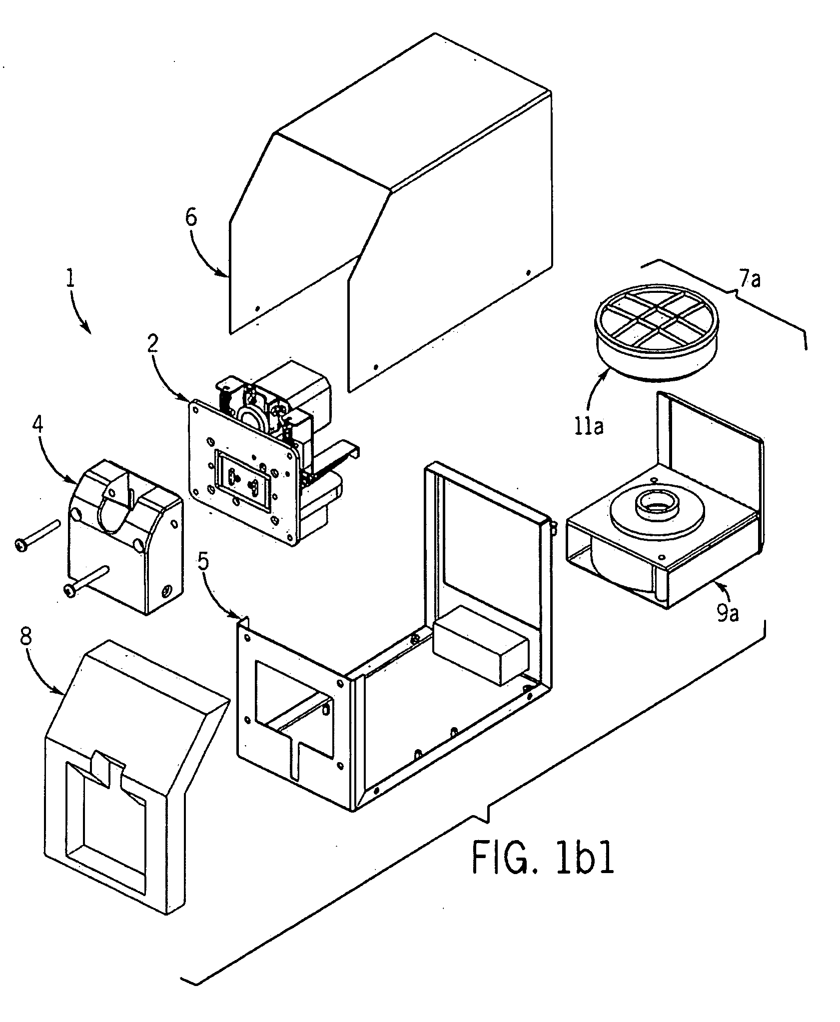
[0048]Staking device 1, as shown in FIGS. 1a1 and 1a2, is described in terms of permanently attaching a thermoplastic label that has been provisionally attached to a tissue cassette made of thermoplastic material. Those skilled in the art understand that various modifications to the device can be made to accommodate labels and substrates comprising other materials and designs. Various items of equipment such as electrical connections, circuit boards, power supplies, fittings and the like have been selectively omitted so as to simplify the drawings. The following description does not limit the scope of the device, but particularly points out several embodiments. Additionally, like numerals have been used to identify like parts throughout.

[0049]The staking device 1 creates a collar bond 33 that bonds a label 53 to a label-bearing face 19 of a substrate 24 (see FIG. 12c). The collar bond 33 as referenced in this application is defined as a substrate 24 that has been melted and displace...


PUM

PropertyMeasurementUnit
rotationaaaaaaaaaa
pressureaaaaaaaaaa
heataaaaaaaaaa

Abstract

Labels are permanently attached to a substrate, e.g., a tissue cassette, by use of a staking device. The device comprises a staker assembly and a cassette fixture assembly. The cassette fixture assembly includes a slot and a clamping assembly for securing the cassette within the device. The staker assembly includes a set of probes that are heated and sequentially moved into a position to burn a hole in a label that is provisionally attached to the cassette, and then the substrate is melted and displaced through the hole to form a collar bond that permanently attaches the label to the cassette. The label remains attached to the cassette when exposed to harsh environmental conditions, e.g., high heat, high humidity, solvents, etc.

Description

CROSS-REFERENCE TO RELATED APPLICATION[0001]This application is a continuation-in-part application of U.S. application Ser. No. 11 / 470,300 filed on Sep. 6, 2006 and claims priority to U.S. Provisional Application Ser. No. 60 / 986,169 filed on Nov. 7, 2007 and U.S. Provisional Application Ser. No. 61 / 028,647 filed on Feb. 14, 2008.FIELD OF THE INVENTION[0002]This invention relates to a device or machine for attaching a label to a substrate. In one aspect, the invention relates to a device for mechanically attaching a label to a substrate while in another aspect, the invention relates to a device comprising at least one heated probe and at least one cassette fixture assembly. In yet another aspect, the invention relates to a method of using the device.BACKGROUND OF THE INVENTION[0003]In the field of identification, labeling is commonly employed. One common form of the label consists of a (i) middle or substrate layer, e.g., film, foil, nonwoven such as Tyvek® (spun-bonded polyolefin), ...

Claims


Application Information

Patent Timeline
Patent Type & Authority Applications(United States)
IPC IPC(8): B32B7/00B65C9/08B32B41/00B29C65/00
CPCB29C65/02Y10T156/1309B29C65/609B29C66/21B29C66/80B29C66/81429B29C66/8322B29K2101/12B29L2031/744B65C7/00B65C9/24B29C65/0681Y10T156/1304B29C66/91212B29C66/91231B29C66/91421B29C66/472Y10T156/1052Y10T156/1785Y10T156/12B29C65/00B29C65/18B29C65/305B29C65/48B29C65/4825B29C66/002B29C66/1122B29C66/3452B29C66/5326B29C66/73921B29C66/8161B29C66/8167B29C66/81815B29C66/8221Y10T428/31504
Inventor SCADDEN, CURTRITZKE, MICHAELGROSZ, JOHNRALEIGH, EDWARD A.TERRILL, ANDREWBROCK, MICHAEL
Owner BRADY WORLDWIDE INC
Why Eureka
Try Eureka