Apparatus for Cooking Food

a technology for cooking food and utensils, applied in the field of utensils for cooking food, can solve the problems of poor production efficiency

Inactive Publication Date: 2009-05-14
ISHINO SEISAKUSHOKK
View PDF15 Cites 6 Cited by
  • Summary
  • Abstract
  • Description
  • Claims
  • Application Information

AI Technical Summary

Benefits of technology

[0006]Therefore, the present applicant provided an air outlet which connects to the outside in an upper portion of the housing, so that air can be naturally discharged or discharged by a blower through damper control when the temperature within the housing is temporarily high, and air is taken in from the outside through the inlet and outlet for eggs in the housing, and thus, the temperature within the housing is lowered, and the temperature within the housing is adjusted so as to remain constant. However, when the temperature is adjusted through discharge of air, air comes into the housing through the inlet and outlet, and therefore, the temperature in the vicinity of the inlet and outlet becomes significantly low in comparison with other portions, and thus, the heating area within the housing becomes small, and there is a risk that the eggs may be cooked unevenly.
[0020]According to these characteristics, it becomes difficult for air discharged from one housing to enter another housing, and therefore, the temperature is not affected between adjacent housings, even in the case where air is individually supplied into the housings from the outside.

Problems solved by technology

In order to mass produce cooked food (particularly semi-boiled eggs and hard-boiled eggs) consumed in large amounts in restaurants and the like according to the prior art, a large number of raw eggs are cooked using a cooking apparatus having a conveyor and a heater devised by the present applicant, instead of conventional boiling systems which has poor efficiency in production.

Method used


Image

  • Apparatus for Cooking Food
  • Apparatus for Cooking Food
  • Apparatus for Cooking Food

Examples


first embodiment

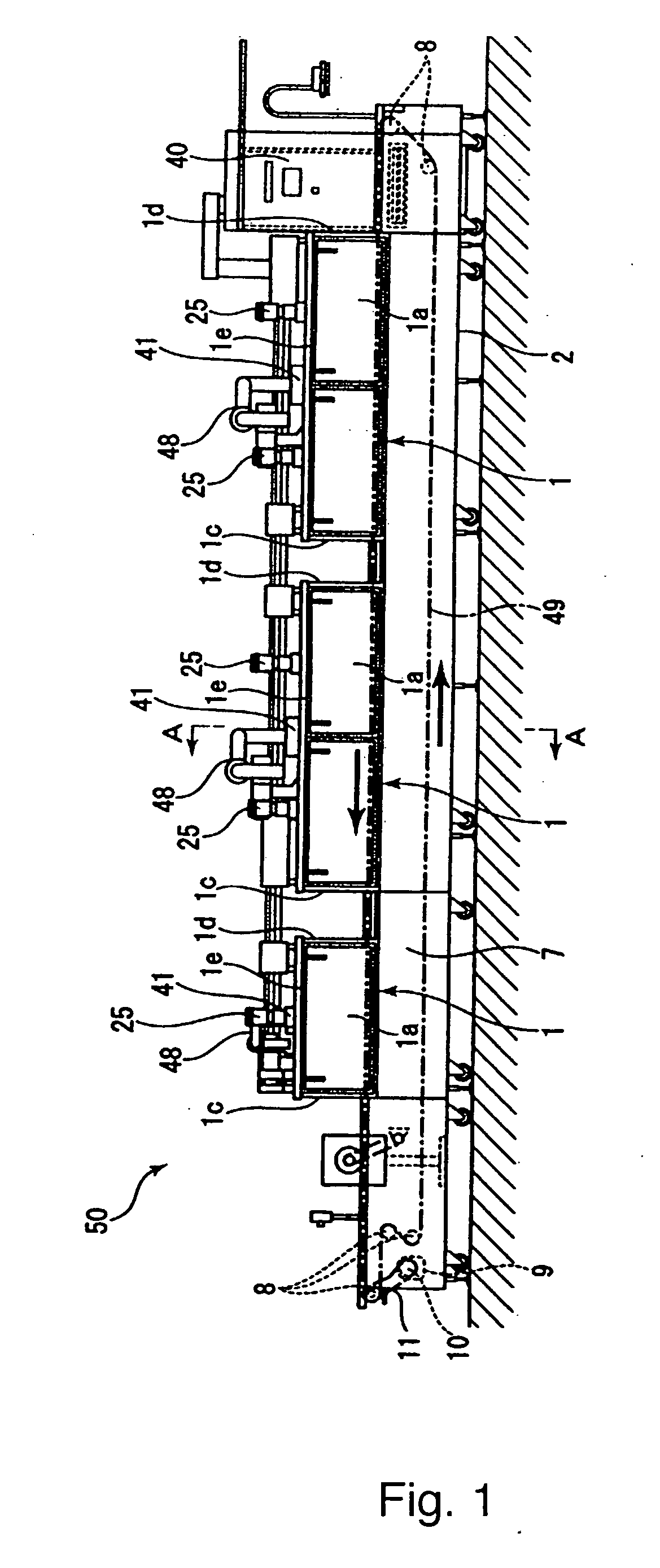
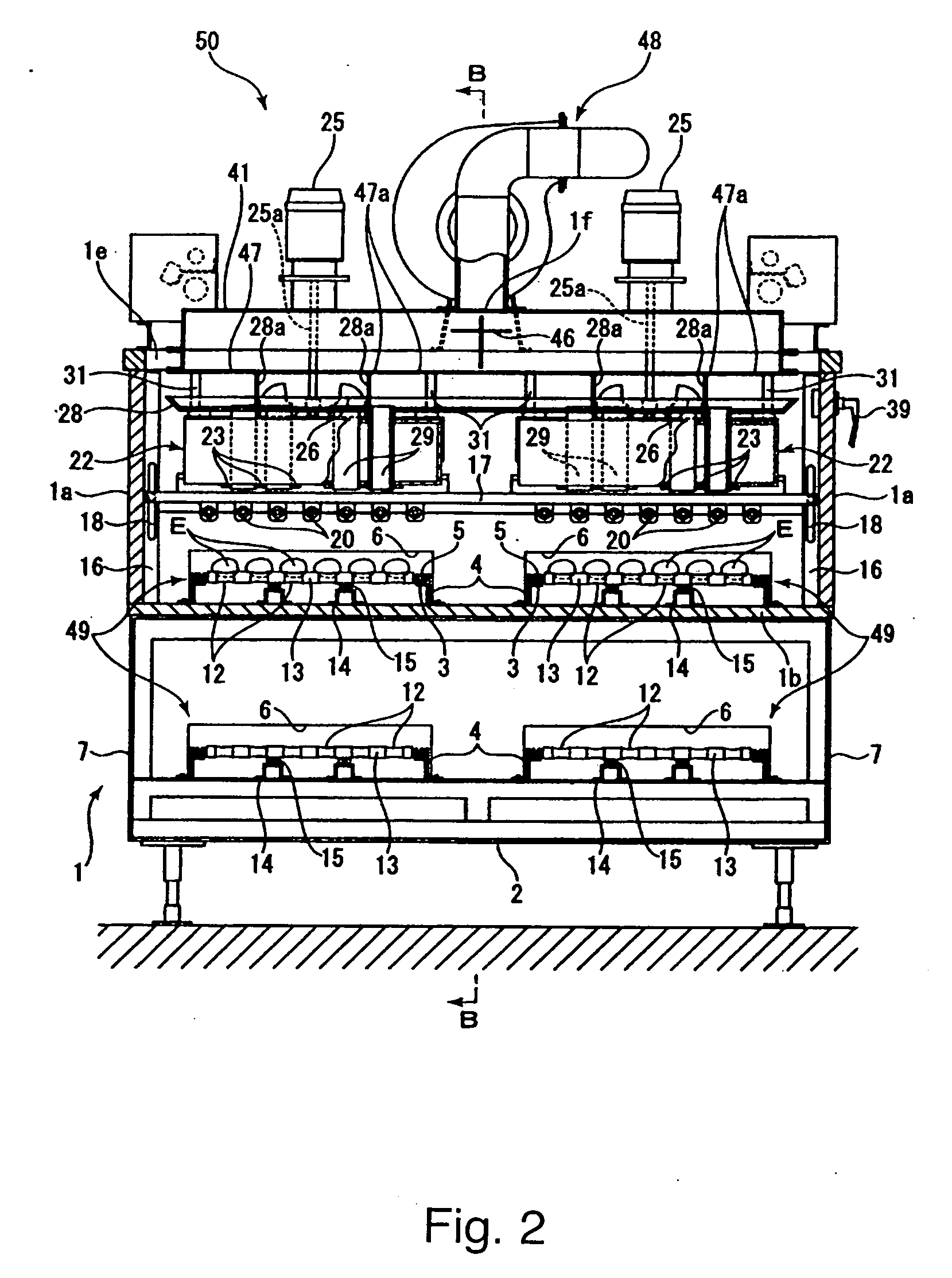
[0078]FIG. 1 is a side diagram showing an image of the entirety of the apparatus for cooking food according to the first embodiment of the present invention, FIG. 2 is a cross sectional diagram showing the inside of the cooking apparatus along line A-A in FIG. 1, FIG. 3 is a perspective diagram showing an air blowing box provided with a number of cylinders for circulating a current, and FIG. 4 is a cross sectional diagram along line B-B in FIG. 2. This cooking apparatus 50 is used when large quantities of food, for example raw eggs, are cooked and processed in sequence, and the food to be cooked is raw eggs E in the present embodiment. Here, the left side in FIG. 1 is the front side of the cooking apparatus 50, and the right side is the rear side of the cooking apparatus 50 in the following description.

[0079]As shown in FIG. 1, the cooking apparatus 50 is mainly formed of a conveyor 49 which can convey raw eggs E and a number of housings 1 in rectangular box form (three in the prese...

second embodiment

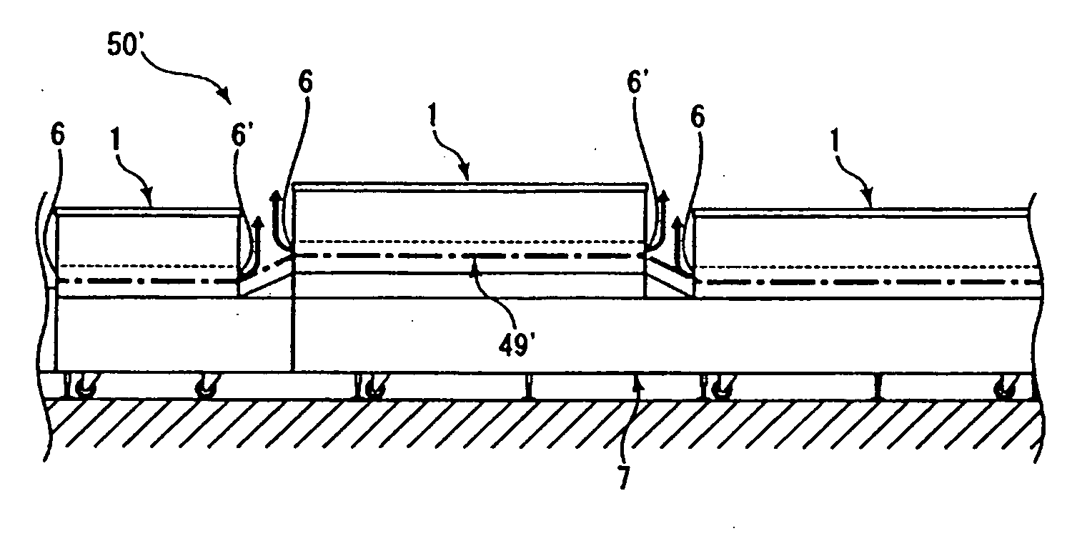
[0112]Next, the cooking apparatus 50′ according to the second embodiment of the present invention is described on the basis of FIG. 5. FIG. 5 is a schematic side diagram showing the cooking apparatus 50′. Here, in the following second embodiment, the same symbols are attached to portions having the same structure as in the above described first embodiment, and thus, detailed descriptions thereof are omitted.

[0113]As shown in FIG. 5, the cooking apparatus 50′ is provided with a number of housings 1, and adjacent housings 1, 1 are at a predetermined distance from each other along the path of conveyance for raw eggs E, and at the same time, the two housings 1, 1 have a shift in the height in the up-down direction, and thus are positioned in such a manner that adjacent outlets 6 and inlets 6′ do not face each other, and as a result, air discharged from the outlet 6 and the inlet 6′ of one housing 1 can be prevented from entering another housing 1. That is to say, it becomes difficult fo...

third embodiment

[0115]Next, the cooking apparatus 50″ according to the third embodiment of the present invention is described on the basis of FIG. 6. FIG. 6 is a schematic plan diagram showing the cooking apparatus. Here, in the following third embodiment, the same symbols are attached to portions having the same structure as in the above described first embodiment, and thus, detailed descriptions thereof are omitted.

[0116]As shown in FIG. 6, the path of conveyance of a conveyor 49″ is curved in the cooking apparatus 50″, so that housings 1, 1 are installed in two portions in the curved path of conveyance in such a manner that there is an angle between the outlet 6 and the inlet 6′ of adjacent housings, and the angle is different for air which is discharged from the outlet 6 and the inlet 6′ (direction of arrows in the figure), and as a result, air discharged from the outlet 6 and the inlet 6′ of one housing is prevented from entering the other housing 1.

[0117]Though the embodiments of the present ...


PUM


Abstract

An apparatus for cooking food capable of quickly regulating the temperature in a housing and not causing uneven heating of food in the housing in the temperature regulation. The apparatus (50) has a housing (1) having a heater (20) in it and provided at a predetermined place in a conveyance route formed by a conveyor (49). The apparatus (50) heats food (E) to be heated by causing it to be conveyed and pass in the housing (1). An air supply opening (1f) is formed in a predetermined place of the housing (1), an air blower (48) is connected to the air supply opening (1f), and outside air can be supplied to the inside of the housing (1) by the air blower (48) via the air supply opening (1f). When the outside air is supplied from the air supply opening (1f), the air in the housing (1) is discharged from an entrance / exit (6, 6′) for the food (E) formed in the housing (1).

Description

TECHNICAL FIELD[0001]The present invention relates to an apparatus for cooking food where food to be cooked, such as raw eggs, is cooked while being carried on a conveyor.BACKGROUND TECHNOLOGY[0002]In order to mass produce cooked food (particularly semi-boiled eggs and hard-boiled eggs) consumed in large amounts in restaurants and the like according to the prior art, a large number of raw eggs are cooked using a cooking apparatus having a conveyor and a heater devised by the present applicant, instead of conventional boiling systems which has poor efficiency in production.[0003]A number of rollers are aligned on the support of this cooking apparatus in the direction of conveyance, and the end portions of the respective rollers on the left and right are connected with endless chains, and thus, the rollers are provided in such a manner to be rotatable and drivable. A housing is provided in the middle of the support with a number of ceramic heaters located above the rollers, and an air...

Claims


Application Information

Patent Timeline
Patent Type & Authority Applications(United States)
IPC IPC(8): A47J27/14A23L15/00
CPCA23L1/0135A47J37/045A47J29/00A23L5/17
Inventor ISHINO, HARUKIITO, YOSHIHARUKUBO, SHIGERU
Owner ISHINO SEISAKUSHOKK
Why Eureka
Try Eureka