
Water heater with ionized ignition and electronic control of temperature

a technology of electronic control and water heater, which is applied in the direction of fluid heater, combustion ignition, combustion process, etc., can solve the problems of increasing the equipment and maintenance cost of the entire system, and achieve the effect of maximizing the utilization of energy

Active Publication Date: 2009-05-14
CALENTADORES DE AMERICA S DE R L DE C V
View PDF9 Cites 11 Cited by
  • Summary
  • Abstract
  • Description
  • Claims
  • Application Information

AI Technical Summary

Benefits of technology

[0009]The water heater of the present invention has been designed in such a way that it has a power input between 10 kW and 40 kW, and a set of seven steel tubes forming a heat transfer collector where the length and diameter of the tubes are specified according to the hot water needs of the user, with the capacity to transfer from 82% to 90% of the input power (heater efficiency) using a corrugated coil with a set of fins that delays the gas outflow and allows for maximum utilization of the energy generated by the burner, at a temperature no greater than 250° C. The entire set of components of the present invention allows the backup heater to operate without a permanently lit pilot light.

Problems solved by technology

To meet the constant demand for hot water with the maximum possible fuel economy, an electronic system was integrated with a set of gas valves that gradually lights the water heater burner in a direct way by means of an electric spark, and a flame detector, like the one cited in PCT patent application WO / 2007 / 057864, however, the water heater described in the aforementioned patent does not adapt itself fully to most hydraulic installations existing in the country, and therefore in many cases it is necessary to adapt or integrate other elements for its operation, increasing the equipment and maintenance cost of the entire system.

Method used


Image

  • Water heater with ionized ignition and electronic control of temperature
  • Water heater with ionized ignition and electronic control of temperature
  • Water heater with ionized ignition and electronic control of temperature

Examples


Embodiment Construction

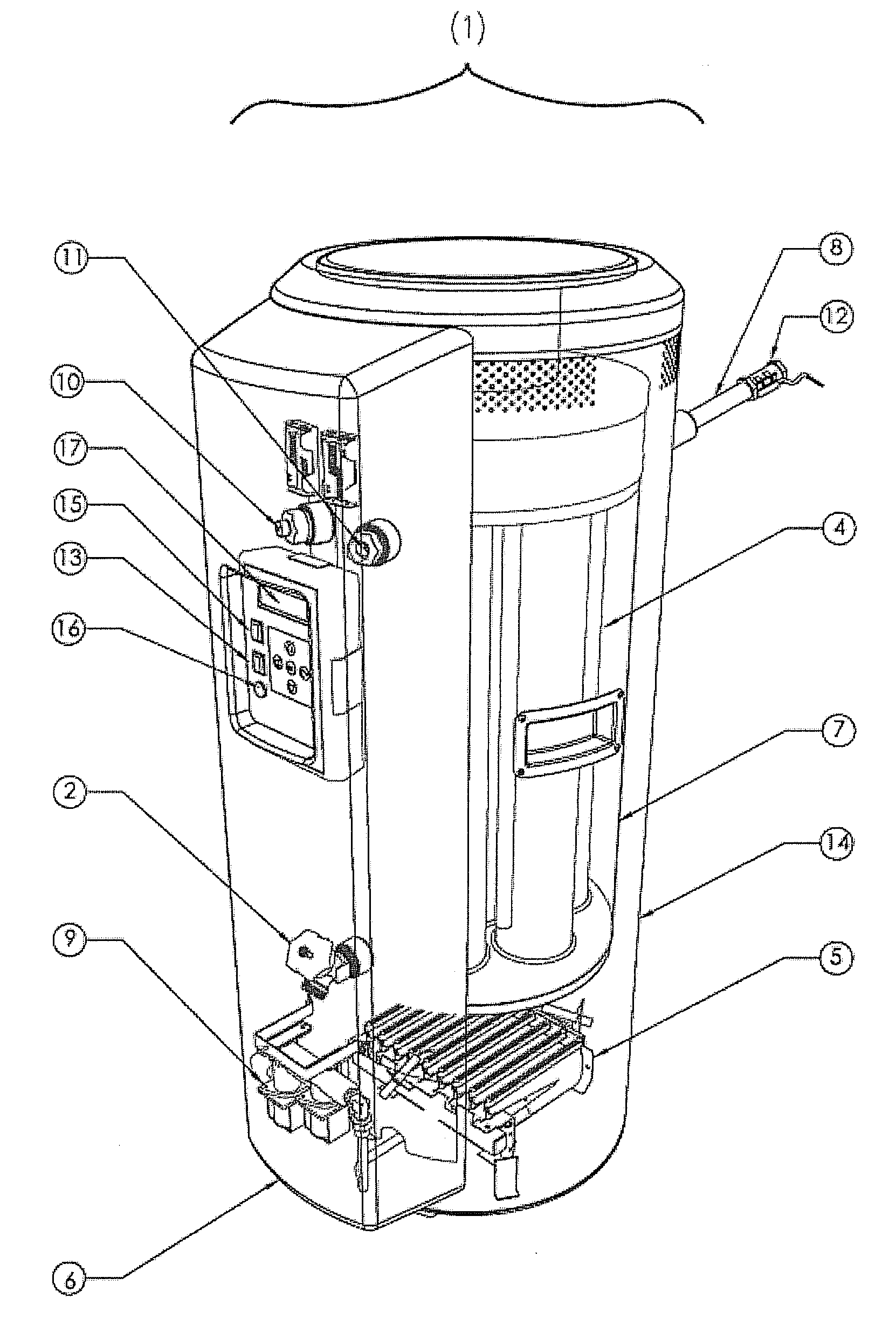
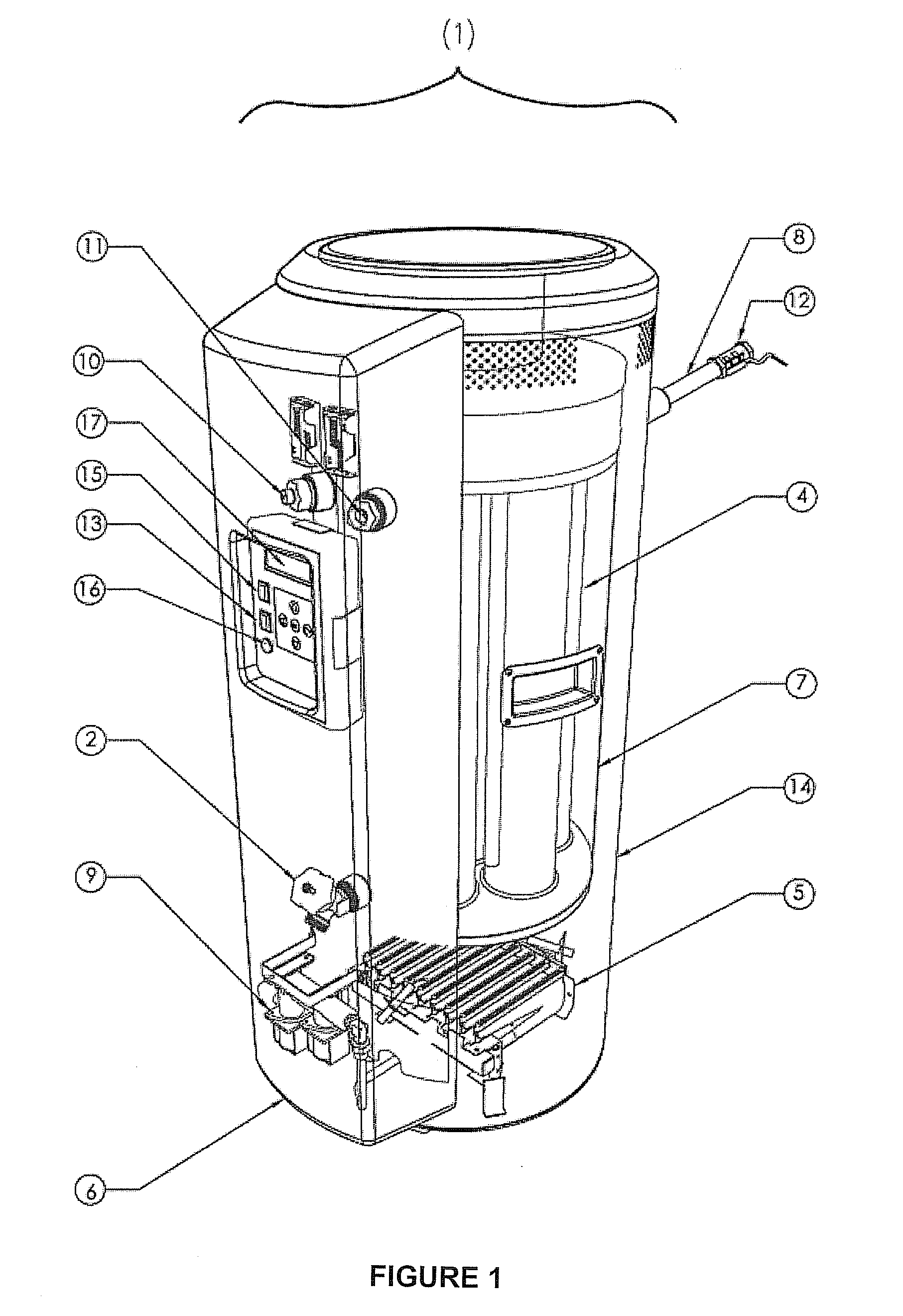
[0014]The heater (1) of the present invention is designed to have only between 15 dm3 (15 liters) and 40 dm3 (40 liters) of internal volume and to withstand a pressure greater than 0.45 MPa. The entire tank (7) is made of steel and the areas in contact with water are porcelainized, depending on the capacity and the needs of the user.

[0015]The water feed is located at the posterior and lower part of tank (7); likewise, the water outlet is located at the upper lateral part of the tank. Additionally, on the lower part of the tank there is a coupling which connects the exterior with the water contained in the tank (7) to place a stopcock or plug (2) allowing for drainage and cleaning of the tank (7).

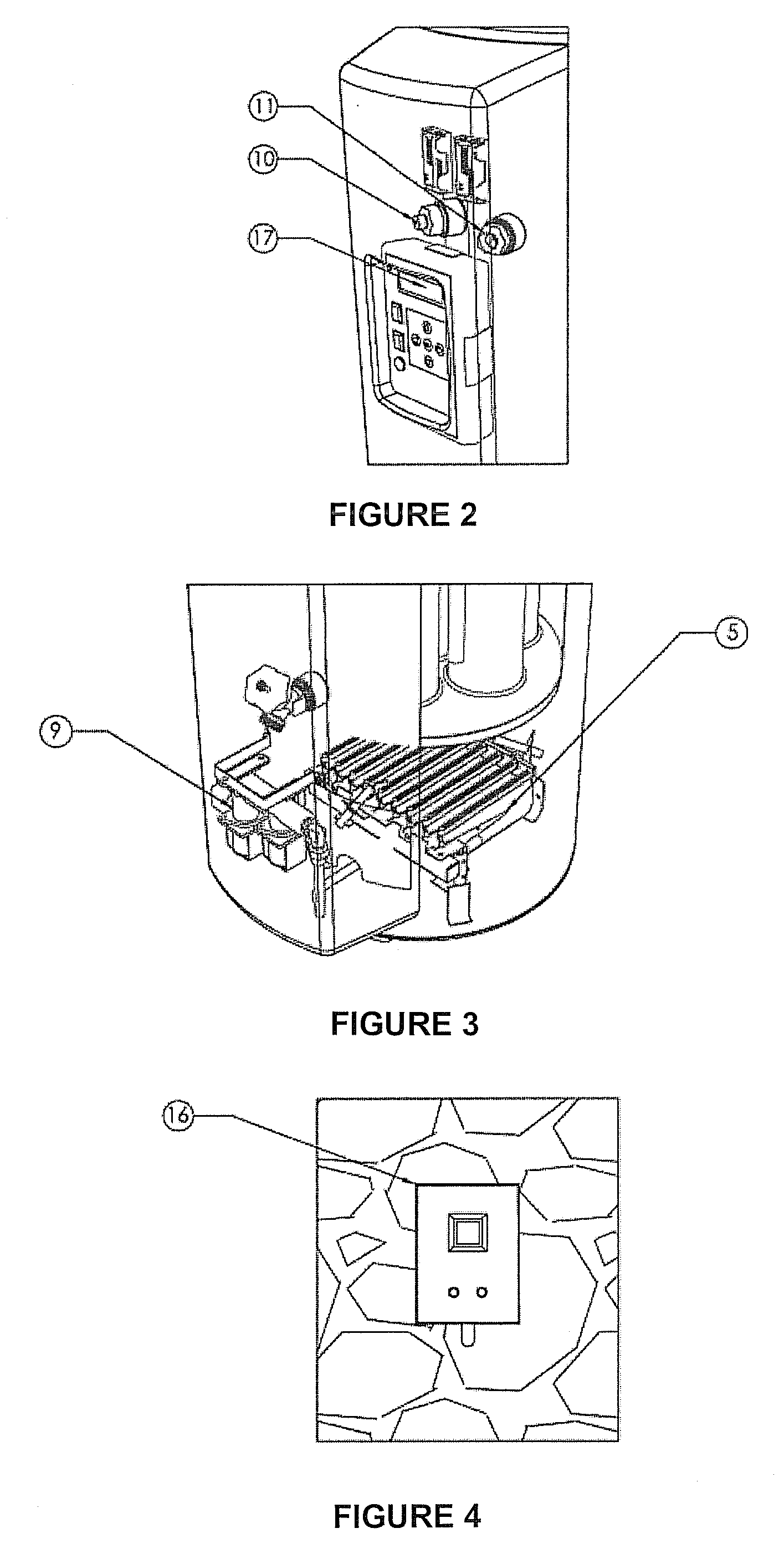
[0016]Power must be supplied to the water heater by means of a burner (5) with nine multi-burners (5) and with a variable nozzle diameter to supply between 10 kW and 40 kW for different types of gases.

[0017]Fuel gas is supplied by means of a system of electrovalves (9), connected to a cast a...


PUM


Abstract

A water heater is controlled by an electronic system that initiates the operation of the heater when a flow detector sends a demand signal for hot water flow to the electronic card, which ignites a burner as function of a temperature programmed by the user. The burner is lit gradually by an electrical spark emitted by a spark plug connected to the electronic card, which in turn controls gas feed to the burner. As soon as the burner is lit, the electric current generated by the first spark plug is transformed by the ionization effect, changing the polarization of the current, which is detected by another spark plug that emits the change signal to the electronic card for further control of the heater. The heater operates without a permanently lit pilot light.

Description

FIELD OF THE INVENTION[0001]The present invention refers generally to water heating equipment with an ionized system that provides a constant water supply. The water heater of the present invention is a versatile piece of equipment that can be used both in pipe equipment and in fin equipment.BACKGROUND OF THE INVENTION[0002]To meet the constant demand for hot water with the maximum possible fuel economy, an electronic system was integrated with a set of gas valves that gradually lights the water heater burner in a direct way by means of an electric spark, and a flame detector, like the one cited in PCT patent application WO / 2007 / 057864, however, the water heater described in the aforementioned patent does not adapt itself fully to most hydraulic installations existing in the country, and therefore in many cases it is necessary to adapt or integrate other elements for its operation, increasing the equipment and maintenance cost of the entire system.[0003]The water heating system has ...

Claims


Application Information

Patent Timeline
IPC IPC(8): F24H4/02
CPCF23N5/042F23N5/123F23N2027/02F24H9/2035F23N2031/12F23N2031/20F23N2041/04F23N2027/36F23N2227/02F23N2231/12F23N2227/36F23N2231/20F23N2241/04F24H15/223F24H15/36F24H15/172F24H15/281F24H15/238F24H15/31F24H15/395F24H15/45F24H15/128F24H15/174
Inventor LOPEZ, MOISES ALEJANDRO AVINAGONZALEZ, ALEJANDRO SANCHEZESCALANTE, HECTOR ABRAHAM CISNEROS
Owner CALENTADORES DE AMERICA S DE R L DE C V
Learn More