Hydraulic brake lever

a brake lever and hydraulic technology, applied in the field of brake levers, can solve the problems of complex and time-consuming manufacturing of conventional brake levers, inability to meet the demands of bicycle industry and consumers, and high manufacturing costs, so as to reduce manufacturing costs, reduce manufacturing costs, and reduce manufacturing costs

Inactive Publication Date: 2009-05-14
LEE CHI ENTERPRISES
View PDF5 Cites 43 Cited by
  • Summary
  • Abstract
  • Description
  • Claims
  • Application Information

AI Technical Summary

Benefits of technology

[0008]A hydraulic brake lever in accordance with the present invention comprises a body having a bladder chamber, a cavity and a flexible separator mounted between the bladder chamber and the cavity. The flexible separator holds the hydraulic oil in the front section of the body and prevents a rear section of the body from contacting with the pressu

Problems solved by technology

Thus, manufacturing the conventional brake lever is complicated and time-consuming and a manufa

Method used


Image

  • Hydraulic brake lever
  • Hydraulic brake lever
  • Hydraulic brake lever

Examples


Embodiment Construction

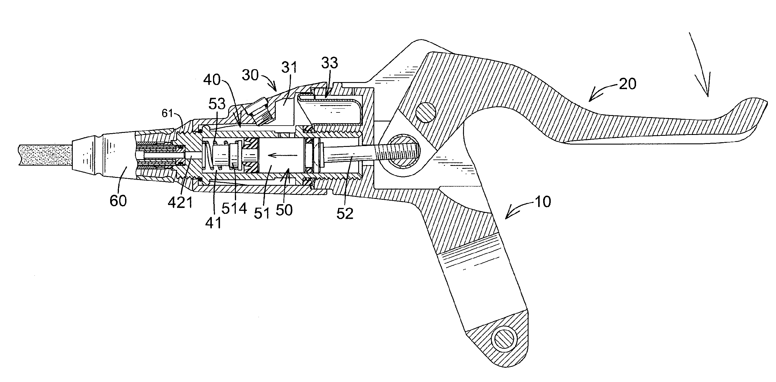
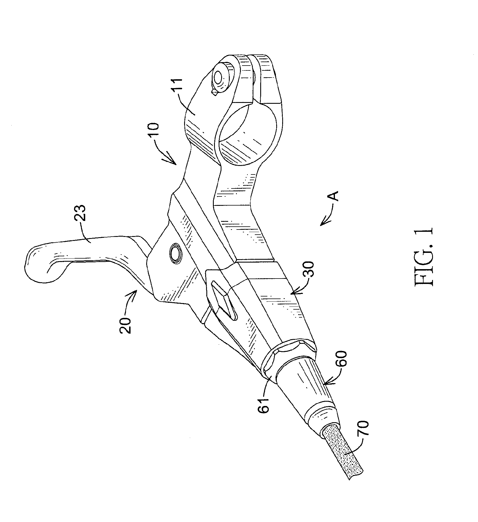
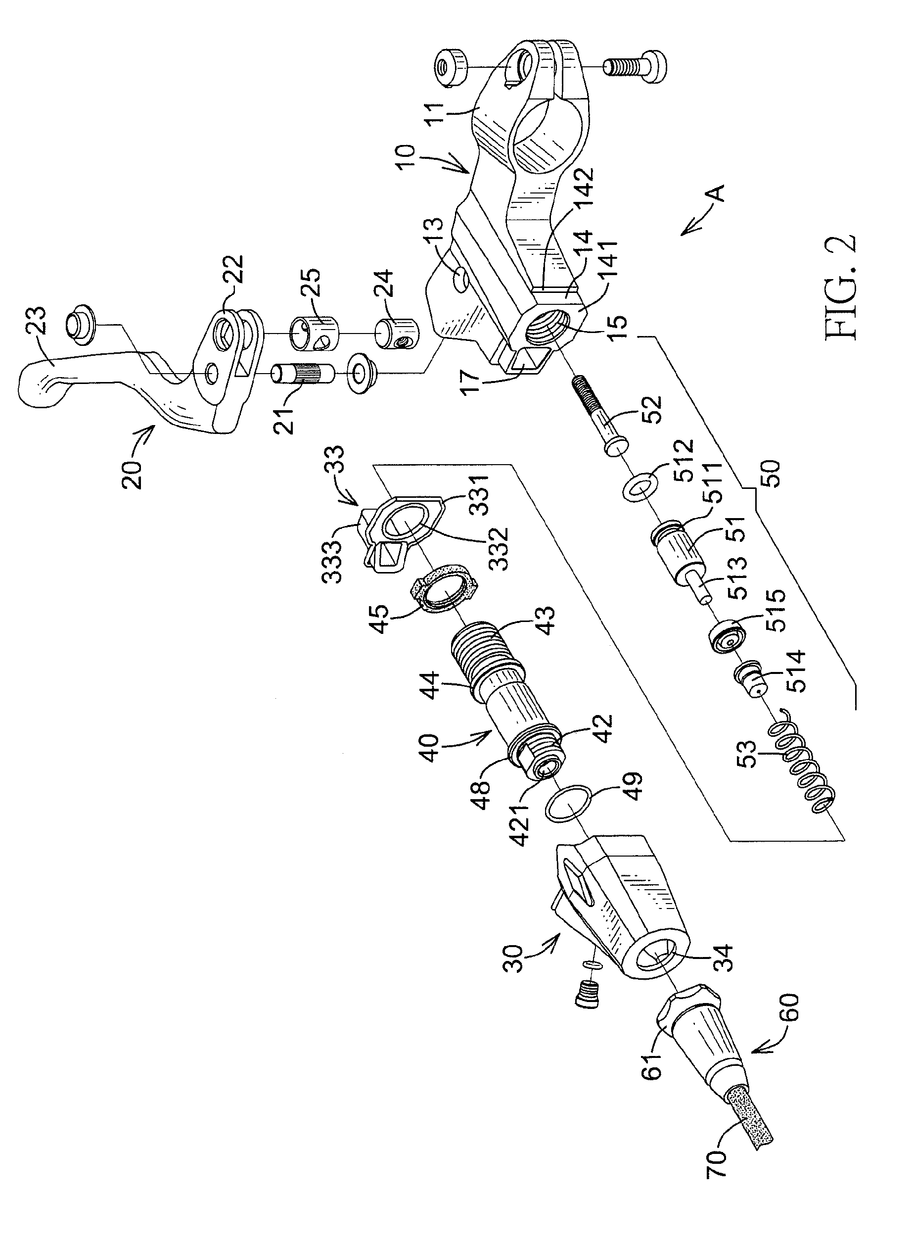
[0015]With reference to FIGS. 1 to 3, a hydraulic brake lever in accordance with the present invention comprises a body (A), a lever bar (20), a cylinder (40), a piston set (50), a cover (60) and a hydraulic tube (70).

[0016]The body (A) has a front section and a rear section, may be formed integrally as one piece and may comprise a base member (10), a flexible separator (33) and a cavity member (30). The base member (10) may be manufactured as one piece by die-casting and is disposed in the rear section of the body (A). The base member (10) has a front end, a rear end, two sides, a connecting section (11), a mounting groove (12), a pivoting hole (13), an abutting section (14), a receiving chamber (15), a rod hole (16) and a bladder chamber (17). The connecting section (11) is formed in one of the sides of the base member (10) and may be mounted on a handle bar of a bicycle. The mounting groove (12) is formed in the other side of the base member (10). The pivoting hole (13) is define...


PUM


Abstract

A hydraulic brake lever includes a body having a bladder chamber, a cavity and a flexible separator mounted between the bladder chamber and the cavity. The flexible separator holds hydraulic oil in a front section of the body and prevents a rear section of the body from contacting with the pressurized hydraulic oil. A cylinder is mounted in the cavity of the body and accommodates a piston set. Thus, a high pressure is kept in the cylinder and is not applied directly on the body. Due to the separating design, the hydraulic oil applied a low pressure on the body. Thus, manufacturing the body is less limited and a manufacturing cost is reduced.

Description

BACKGROUND OF THE INVENTION[0001]1. Field of Invention[0002]The present invention relates to a brake lever, and more particularly to a hydraulic brake lever using a flexible separator to hold hydraulic oil in a front section of the hydraulic brake lever.[0003]2. Description of the Related Art[0004]Because a hydraulic brake system has a high brake force and can provide safe and stable brake effects, the hydraulic brake system is often used on high priced bicycles. A conventional hydraulic brake system comprises a brake lever mounted on a handlebar of a bicycle, a disc brake mounted beside a wheel of the bicycle and a hydraulic tube connected to the brake lever and the disc brake.[0005]A conventional brake lever comprises a body have a cavity and an oil chamber for accommodating a piston set and hydraulic oil. Because the brake lever will apply a high pressure on the hydraulic oil when braking, the body must be manufactured by forging to prevent the body from breaking or leaking. Thus...

Claims


Application Information

Patent Timeline
IPC IPC(8): B60T11/00
CPCB60T7/10B60T11/22B62K23/06B62L3/023B62M25/08
Inventor LIN, YI-HSIENKE, SHIH-CHING
Owner LEE CHI ENTERPRISES
Why Eureka
Try Eureka