Machine tool

a technology of machine tools and movable units, applied in the field of machine tools, can solve the problems of affecting the horizontal movement of the movable unit, the prone flexing of the upper guide rail, and the difficulty of moving the movable unit stably and smoothly at a high speed from side to side, and achieve the effect of stably

Active Publication Date: 2009-05-14
DMG MORI SEIKI CO LTD
View PDF4 Cites 23 Cited by
  • Summary
  • Abstract
  • Description
  • Claims
  • Application Information

AI Technical Summary

Benefits of technology

[0011]It is an object of the present invention to provide a machine tool including a double column frame extending from side to side and comprising a pair of vertical columns and a beam extending from side to side between the columns, and a movable unit having a tool rest and movable from side to side along the double column frame, the movable unit being capable of moving stably and smoothly at

Problems solved by technology

The upper guide rail is also liable to flex downwardly, and the movable unit as it moves horizontally is adversely affected by the deformation of the upper guide rail.
As a result, it is difficult to move the movable unit stably and smoothly at a high speed from side to side, and the accurac

Method used


Image

  • Machine tool
  • Machine tool
  • Machine tool

Examples


Embodiment Construction

[0037]Like or corresponding parts are denoted by like or corresponding reference characters throughout views.

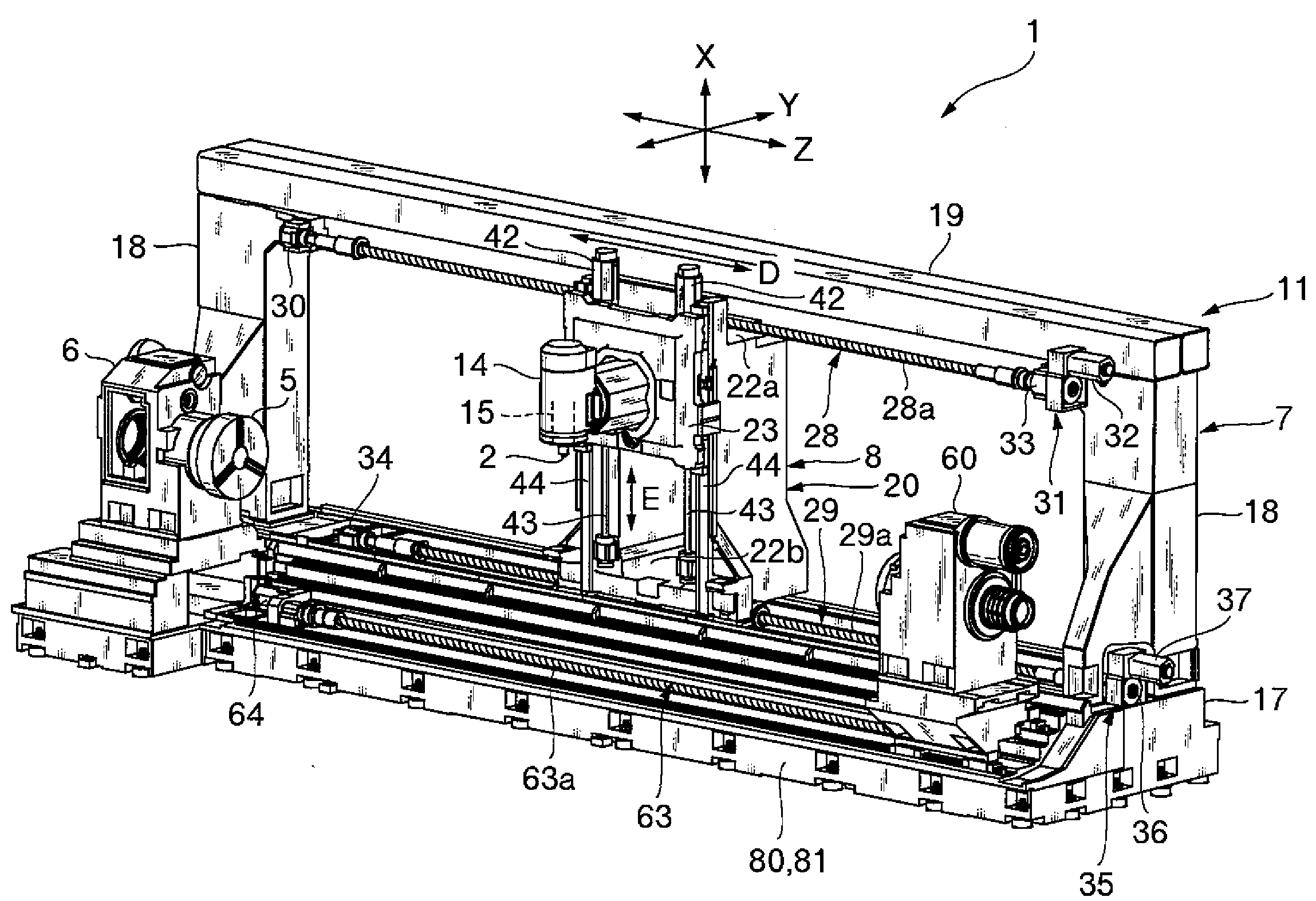
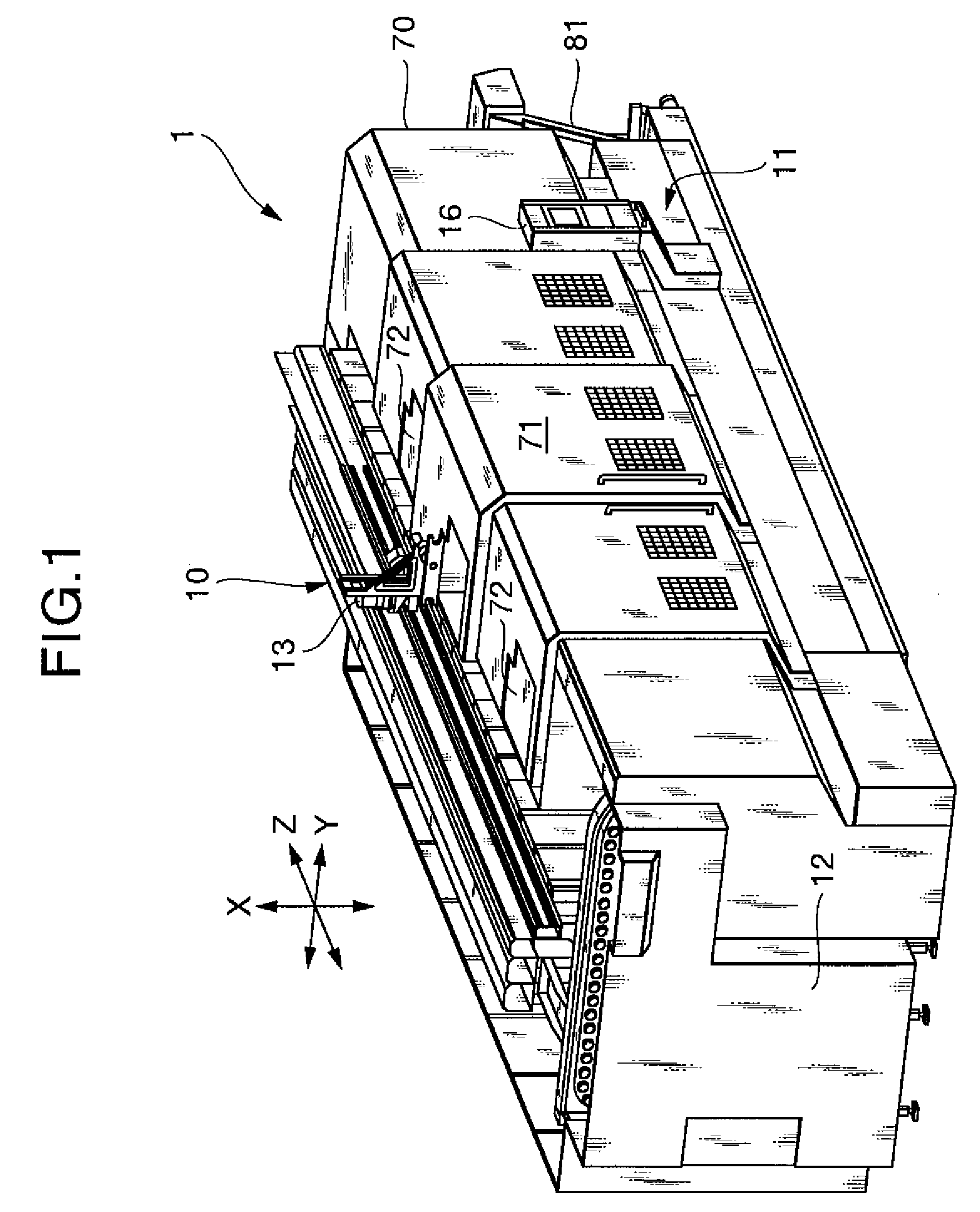
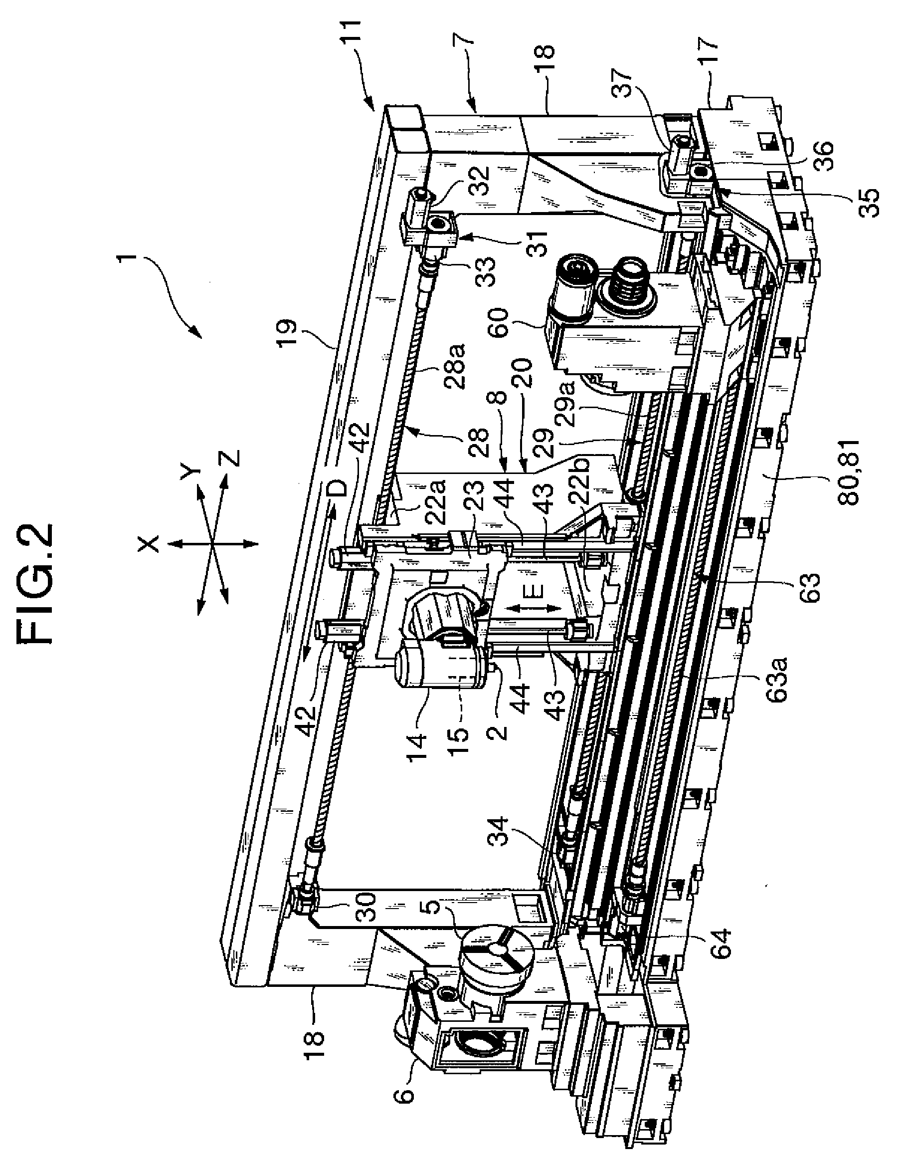
[0038]A machine tool according to the present invention includes a pair of horizontally spaced columns vertically mounted on a bed and a beam extending horizontally between upper portions of the columns. The columns and the beam jointly make up a double column frame which is horizontally elongate and disposed on the bed. A movable unit having a tool rest is horizontally movable along the double column frame.

[0039]The machine tool includes a pair of guide rails and upper and lower ball screws. The guide rails are mounted on the bed and spaced from each other in a direction perpendicular to the direction in which the movable unit is horizontally movable. The guide rails extend horizontally parallel to each other. The movable unit is horizontally movably supported on the guide rails. The upper and lower ball screws are mounted respectively on upper and lower portions of the doub...


PUM


Abstract

A machine tool has a pair of guide rails and a pair of upper and lower ball screws. No forces are transferred between a beam of a double column frame and a movable unit. The guide rails are spaced from each other and disposed on a bed, and the movable unit is horizontally movably supported on the guide rails. The upper and lower ball screws are mounted respectively on upper and lower portions of the double column frame for moving the movable unit horizontally. Even when the beam is deformed by flexing downwardly by gravity, the movable unit moves stably and smoothly at a high speed to machine a workpiece highly accurately without being adversely affected by the deformation of the beam.

Description

BACKGROUND OF THE INVENTION[0001]1. Field of the Invention[0002]The present invention relates to a machine tool including a double column frame extending horizontally from side to side as viewed in front elevation and a movable unit having a tool rest and movable horizontally from side to side along the double column frame.[0003]2. Description of the Related Art[0004]Japanese laid-open patent publication No. 2006-263861 discloses a machine tool including a double column frame extending from side to side as viewed in front elevation and a movable unit having a tool rest and movable from side to side along the double column frame. The double column frame comprises a pair of horizontally spaced columns, an upper beam interconnecting the upper ends of the columns, and a lower beam interconnecting the lower ends of the columns. The double column frame can be manufactured as an integral casting as it has a small horizontal length.[0005]The upper and lower beams have respective upper and l...

Claims


Application Information

Patent Timeline
IPC IPC(8): F16M13/00
CPCB23B3/065B23B5/08B23Q1/015B23Q1/017B23Q1/26Y10T29/5114B23Q1/626B23Q39/02B23Q2039/008Y10T82/2508B23Q1/58
Inventor YASUDA, HIROSHIHASHIMOTO, HIROSHI
Owner DMG MORI SEIKI CO LTD
Why Eureka
Try Eureka