Current Measuring Apparatus

a current measuring and current technology, applied in the direction of measuring devices, measuring using dc-ac conversion, instruments, etc., can solve the problems of reducing the size of the apparatus, reducing the effect of the circuit or configuration, and so as to reduce the effect of reducing the adverse effect of the current flowing

Active Publication Date: 2009-05-14
ASAHI KASEI ELECTRONICS CO LTD
View PDF8 Cites 87 Cited by
  • Summary
  • Abstract
  • Description
  • Claims
  • Application Information

AI Technical Summary

Benefits of technology

[0014]The apparatus may further comprise electromagnetic shield means provided on the conductor different from the measurement target conductor. Application of a magnetic shield such as winding of a magnetic substance or the like enables a further reduction in the adverse effect of a current flowing through the different conductor.
[0015]The magnetic sensing direction of each of the magnetic sensors may be inclined through an angle such that the magnetic sensor is located level to the plane and is insensitive to a magnetic field generated by a current flowing through an adjacent conductor. For example, the magnetic sensor is slightly inclined so as to be insensitive to the direction of the synthetic m...

Problems solved by technology

To measure a multiphase current flowing through an inverter or the like, it is difficult to accurately measure a current in each phase using a small apparatus that uses a magnetic sensor.
This disadvantageously prevents a reduction in the size of the apparatus.
However, these techniques co...

Method used


Image

  • Current Measuring Apparatus
  • Current Measuring Apparatus
  • Current Measuring Apparatus

Examples


embodiment 1

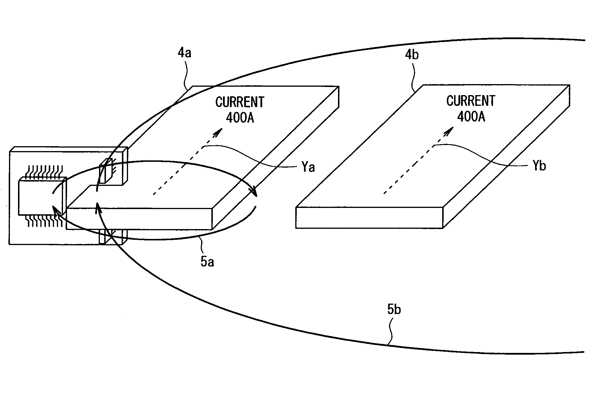
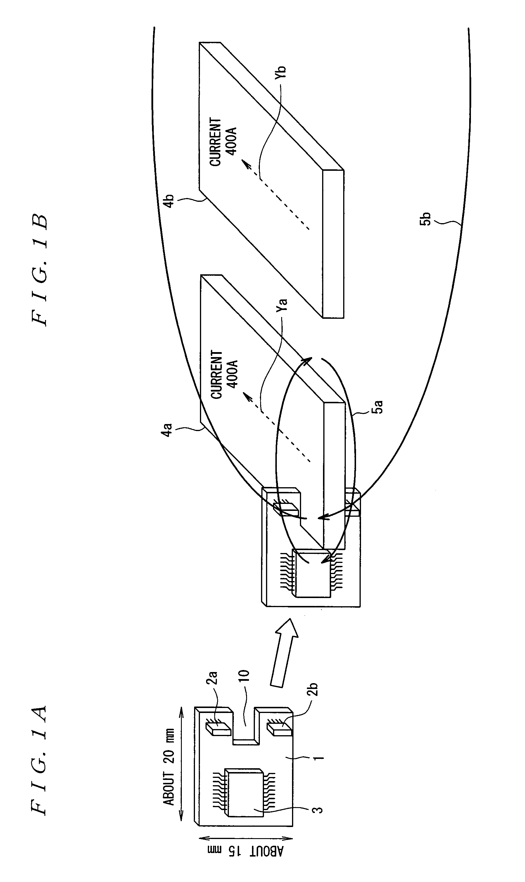
[0048]FIG. 5 shows the configuration of Embodiment 1 of the current measuring apparatus in accordance with the present invention. In FIG. 5A, the three bus bars 4a, 4b, 4c are provided adjacent and substantially parallel to one another. Of the three bus bars 4a, 4b, 4c, the bus bar 4a, located at the end, is inserted in the recessed portion of the printed circuit board 1a. The printed circuit board 1a has the Hall elements 2a and 2b and the signal processing integrated circuit 3 as in the case of FIG. 1. Similarly, the bus bar 4c, located at the opposite end, is placed in the recessed portion of the printed circuit board 1b.

[0049]Here, FIG. 5B shows that the bus bar 4a is inserted in the recessed portion of the printed circuit board 1a. As shown in FIG. 5B, the printed circuit board 1a has long sides of about 20 mm and short sides of about 15 mm. Each of the bus bars 4a to 4c has a width of 13 mm and a thickness of 1.8 mm. Further, the printed circuit board 1a has the recessed port...

embodiment 2

[0052]As shown in FIG. 6A, slot portions 11a to 11c may be formed in the single printed circuit board 1a so that the bus bars can be inserted into the slot portions 11a to 11c. In this case, as shown in FIG. 6B, currents can be measured as is the case with FIG. 5 by fixedly inserting the bus bars 4a to 4c into the corresponding slot portions 11a to 11c in the printed circuit board 1a. In the present example, using the single printed circuit board 1a to construct the current measuring apparatus enables the bus bars and the Hall elements 2a and 2b to be easily positioned.

embodiment 3

[0053]The adverse effect of the central bus bar on the outer bus bars can be reduced by winding a magnetic substance, as a shield, around the immediately adjacent bus bar, which makes the maximum impact. For example, as shown in FIG. 7, the magnetic substance 6 is provided on one of the three bus bars 4a, 4b, 4c, that is, the central bus bar 4b. The present example adopts a configuration in which the bus bar 4b is inserted into the slot portion of the magnetic substance 6. The bus bar 4b is not the measurement target, so that a gap in which the printed circuit board is provided need not be provided in the magnetic substance 6. This enables a size reduction, allowing an increase in the entire size of the apparatus to be inhibited.

[0054]Providing the magnetic substance 6 makes it possible to eliminate the adverse effect of the immediately adjacent bus bar, allowing a reduction in the adverse effect on the Hall elements to at most 1%.


PUM


Abstract

The present invention provides a current measuring apparatus having an improved structure to inhibit the possible adverse effect of a current in a different phase and the possible generation of an induced electromotive force caused by a measurement target current, enabling the measurement target current to be accurately detected even with the small size of the apparatus. The current measuring apparatus includes a printed circuit board 1 having Hall elements 2a, 2b and a signal processing integrated circuit 3 mounted thereon, the Hall elements 2a, 2b sensing a magnetic field generated by a current flowing through a current measurement target bus bar 4a, the signal processing integrated circuit 3 processing sensing outputs from the Hall elements 2a, 2b to calculate a value for the current flowing through the bus bar 4a. Magnetic sensing surfaces of the Hall elements 2a, 2b are arranged substantially perpendicularly to the direction of the magnetic field generated by the current flowing through the bus bar 4a. Further, the printed circuit board 1 is fixed to the bus bar 4a so that a circuit board surface of the printed circuit board 1 having a wire electrically connecting the Hall elements 2a, 2b to the signal processing integrated circuit 3 is positioned substantially parallel to the direction of the magnetic field.

Description

TECHNICAL FIELD[0001]The present invention relates to a current measuring apparatus, and in particular, to a current measuring apparatus that accurately measures a multiphase current even with the small size of the apparatus.BACKGROUND ART[0002]To measure a multiphase current flowing through an inverter or the like, it is difficult to accurately measure a current in each phase using a small apparatus that uses a magnetic sensor. A technique of combining a measurement target conductor, a magnetic core, and a magnetic sensor together has often been used to accurately measure the current in each phase without suffering any adverse effect of a magnetic field generated by a current in different phase. A technique has often been used which involves placing a printed circuit board with a signal processing integrated circuit and a magnetic sensor installed thereon in a gap in the core. In this case, the magnetic core is integrated with a printed circuit board. This disadvantageously prevent...

Claims


Application Information

Patent Timeline
IPC IPC(8): G01R15/18
CPCG01R15/202
Inventor SHIBAHARA, KOJI
Owner ASAHI KASEI ELECTRONICS CO LTD
Why Eureka
Try Eureka