Direct Retinal Display

a retinal display and display technology, applied in the field of direct retinal displays, can solve problems such as limited field of view, and achieve the effect of reducing the misconvergence of the scanned optical beam

Inactive Publication Date: 2009-05-14
HILTON PETER JAMES
View PDF1 Cites 32 Cited by
  • Summary
  • Abstract
  • Description
  • Claims
  • Application Information

AI Technical Summary

Benefits of technology

[0026]Preferably, the elliptical reflecting surface of the converging reflector may be a quasi-elliptical reflecting surface that is shaped to reduce any misconvergence of the scanned optical beam at the pupil of the eye that is caused by the shape of the spherical reflecting surface of the diverging reflector.

Problems solved by technology

Therefore, the field of view is limited by the capabilities of current technologies that determine the scan speed and modulation bandwidth.

Method used


Image

  • Direct Retinal Display
  • Direct Retinal Display
  • Direct Retinal Display

Examples


Embodiment Construction

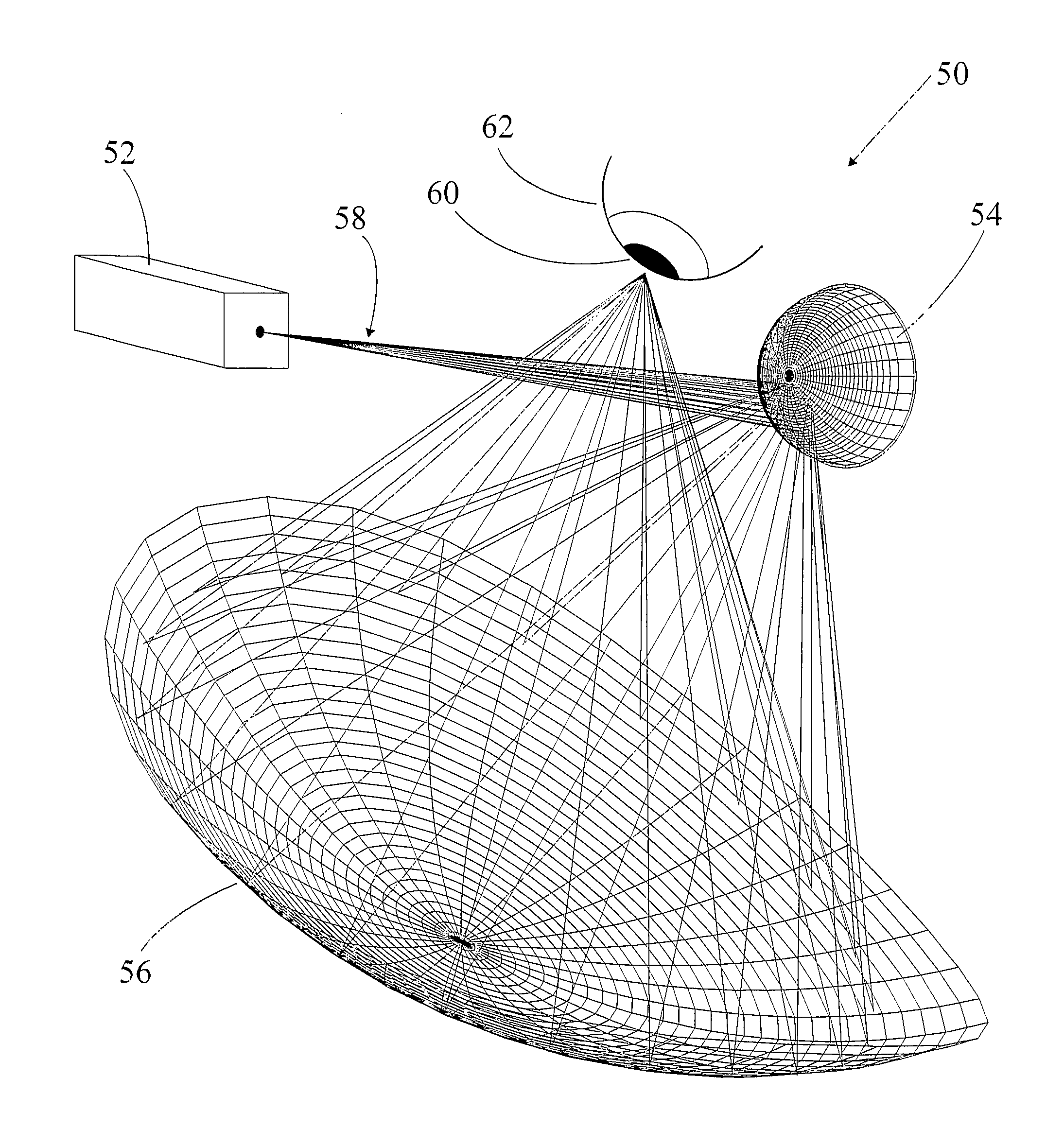
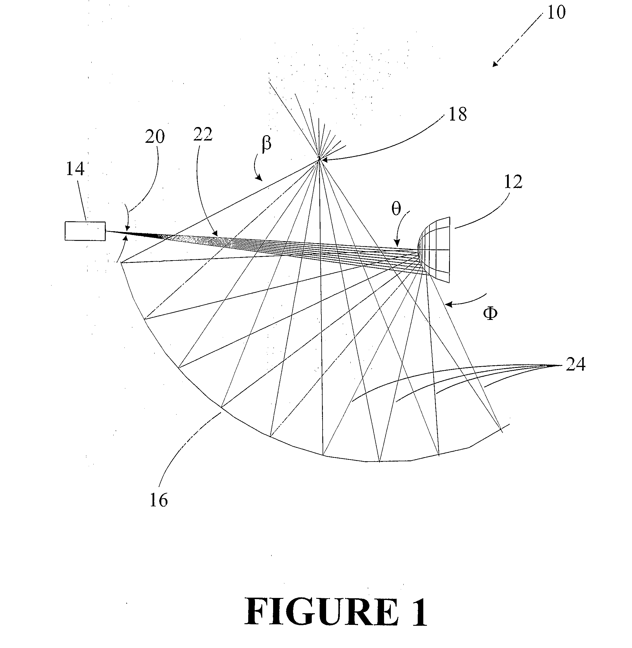
[0057]The present invention relates to a DRD system that produces a wide field of view, for example approximately 100 degrees horizontal and 90 degrees vertical for each eye. The DRD comprises a non-linear and non-paraxial optical design. The DRD enables a wide angle output scan from a relatively small angle input scan. In particular, the DRD utilises a diverging reflector to magnify the angle of a scanned beam from an optical source and a converging reflector to converge the beam scan back to a convergence point or spot that is substantially coincident with the pupil of the eye for reconstructions of the image on the retina of the eye. It will be appreciated that the convergence point or spot may vary in surface area size depending on the specifications of the DRD system. In the preferred form, the convergence spot substantially covers the pupil of the eye.

[0058]Referring to FIG. 1, a preferred embodiment of the DRD apparatus 10 is shown. As mentioned above, the DRD 10 employs non-...


PUM


Abstract

A direct retinal display (50) for displaying an image on the retina of an eye (62) with a wide field of view. The direct retinal display (50) comprises a scan source (52) that is arranged to generate a scanned optical beam (58), modulated with an image, in two dimensions over a scan angle. The direct retinal display (50) further comprises a diverging reflector (54) in the path of the scanned optical beam (58) that is arranged to reflect the scanned optical beam (58) incident on the diverging reflector (54) outwardly with a magnified scan angle toward a converging reflector (56) that is arranged to reflect the scanned optical beam substantially toward a convergence spot at the pupil (60) of the eye (62) for reconstruction and display of the image on the retina with a wide field of view.

Description

FIELD OF THE INVENTION[0001]This invention relates to direct retinal displays (DRDs). In particular, it relates to developments to improve the field of view offered by DRDs.BACKGROUND TO THE INVENTION[0002]DRDs provide an image for viewing by scanning a laser beam or other optical beam modulated with image information directly onto the retina of a user's eye, via the pupil. More particularly, by utilising several colours of laser beams and modulating the intensity of those beams a colour image can be produced on the user's eye. For example, the image is generated sequentially by scanning a light spot in a raster pattern across the retina.[0003]DRDs provide advantages over existing screen based displays. The resolution can be higher and images can be superimposed over real life scenes. This makes DRDs a desirable option for a wide range of applications especially in virtual or augmented reality displays. For example, a DRD in headset form can provide drivers or pilots with informatio...

Claims


Application Information

Patent Timeline
Patent Type & Authority Applications(United States)
IPC IPC(8): G02B26/00
CPCG02B27/0172G02B2027/011G02B2027/0187G02B2027/0132G02B2027/0123
Inventor HILTON, PETER JAMES
Owner HILTON PETER JAMES
Why Eureka
Try Eureka