Measurement of gaps between valve seats and attachment parts

Inactive Publication Date: 2009-05-14
HONDA MOTOR CO LTD
View PDF2 Cites 15 Cited by
  • Summary
  • Abstract
  • Description
  • Claims
  • Application Information

AI Technical Summary

Benefits of technology

[0030]As a result of the above, it is possible to provide a technique for precisely measuring gaps,

Problems solved by technology

If the press-fitting is inadequate, gaps form between the valve seats and the attachment parts.
Therefore, inspections have been unreliable.
It would be difficult in pra

Method used


Image

  • Measurement of gaps between valve seats and attachment parts
  • Measurement of gaps between valve seats and attachment parts
  • Measurement of gaps between valve seats and attachment parts

Examples


Example

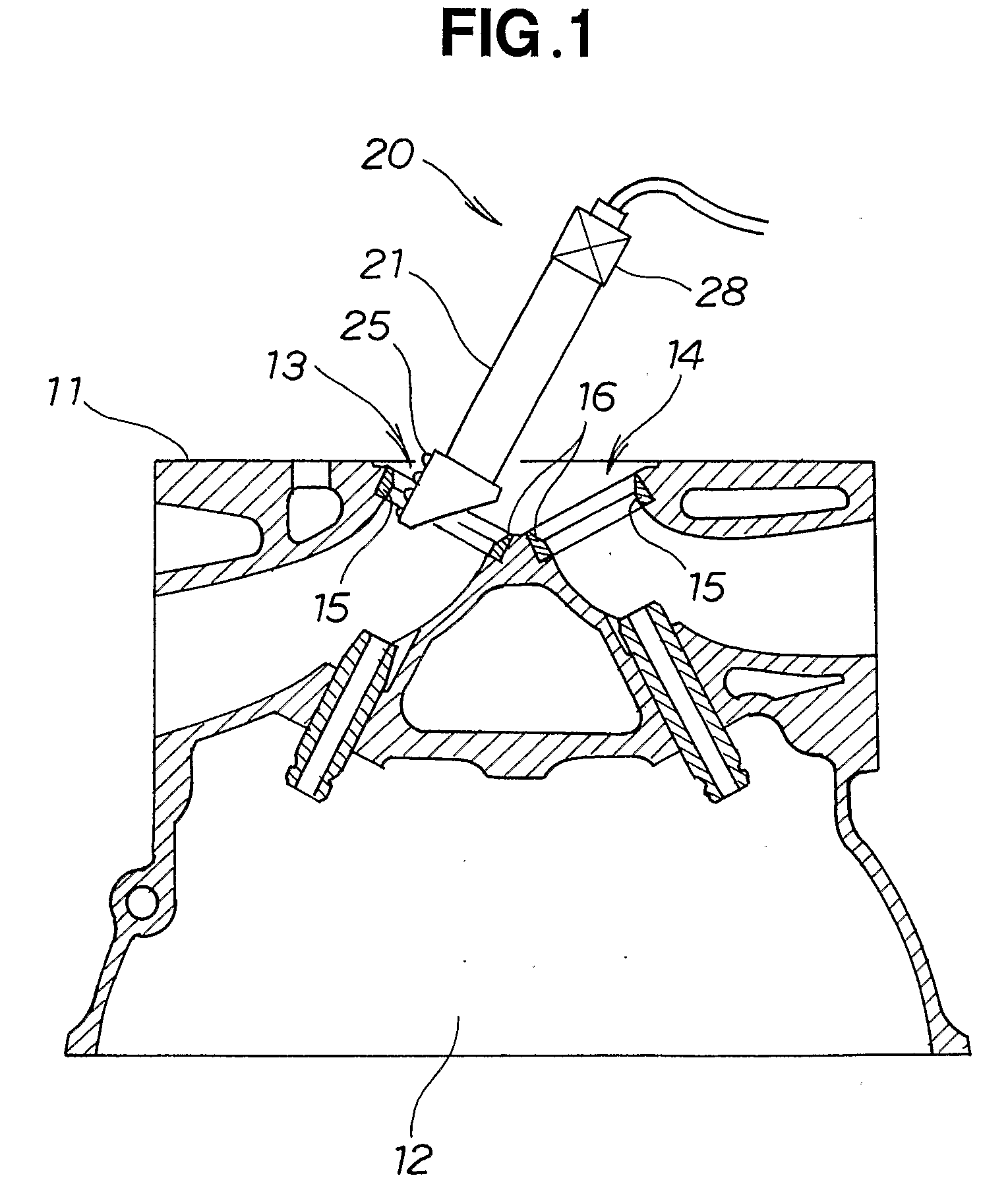
[0041]As shown in FIG. 1, a cylinder head 11 of an engine is turned upside-down so that a valve operating chamber 12 is on the bottom, and an apparatus 20 for measuring gaps between attachment parts and valve seats is partially inserted into an air intake port 13 and an exhaust port 14. Measurements are then conducted with the apparatus 20 for measuring gaps between attachment parts and valve seats. The air intake port 13 is provided with an attachment part 15 by cutting the side nearer to the cylinder head 11, and a valve seat 16 is press-fitted into this attachment part. The same applies to the release port 14.

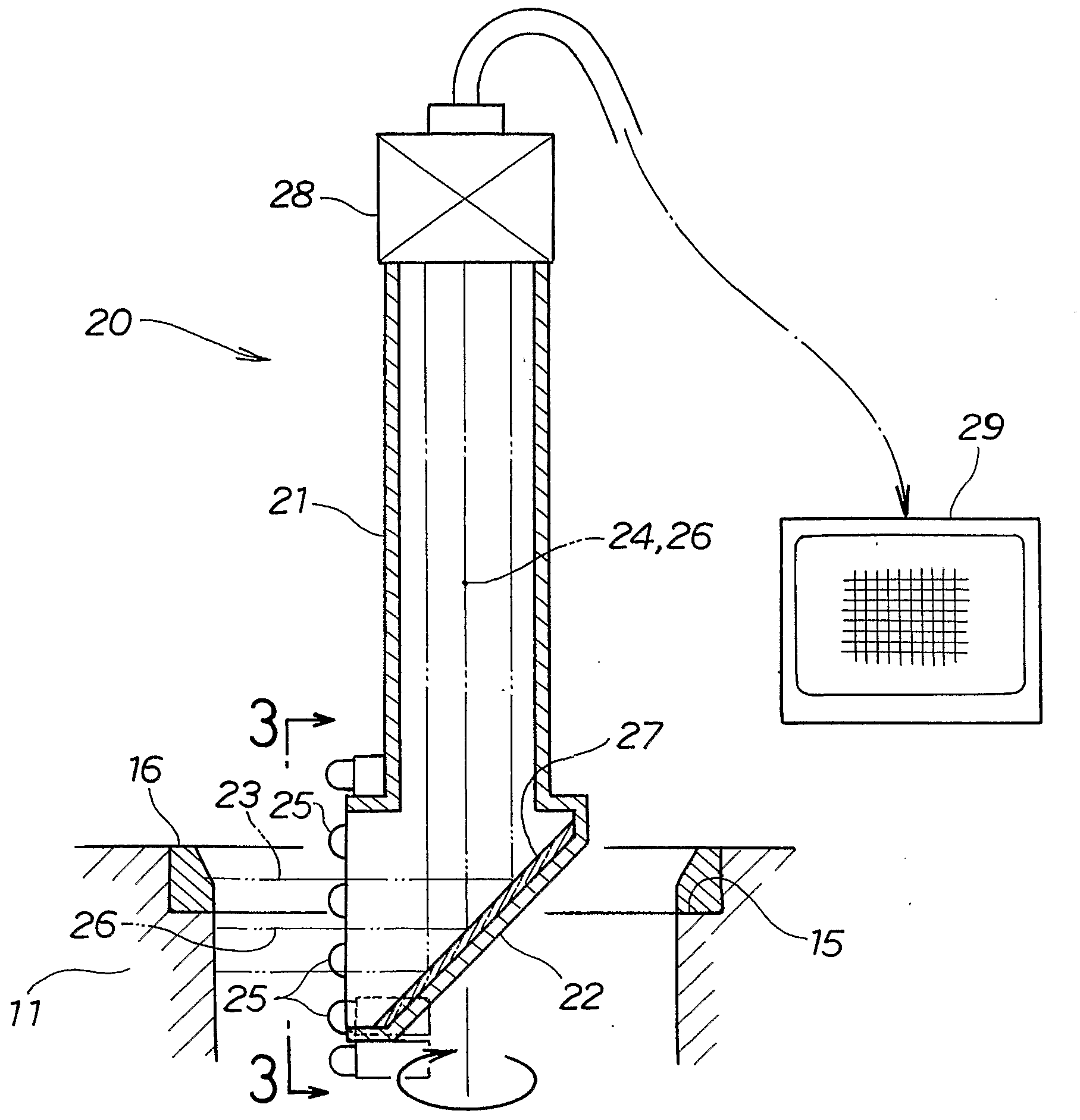
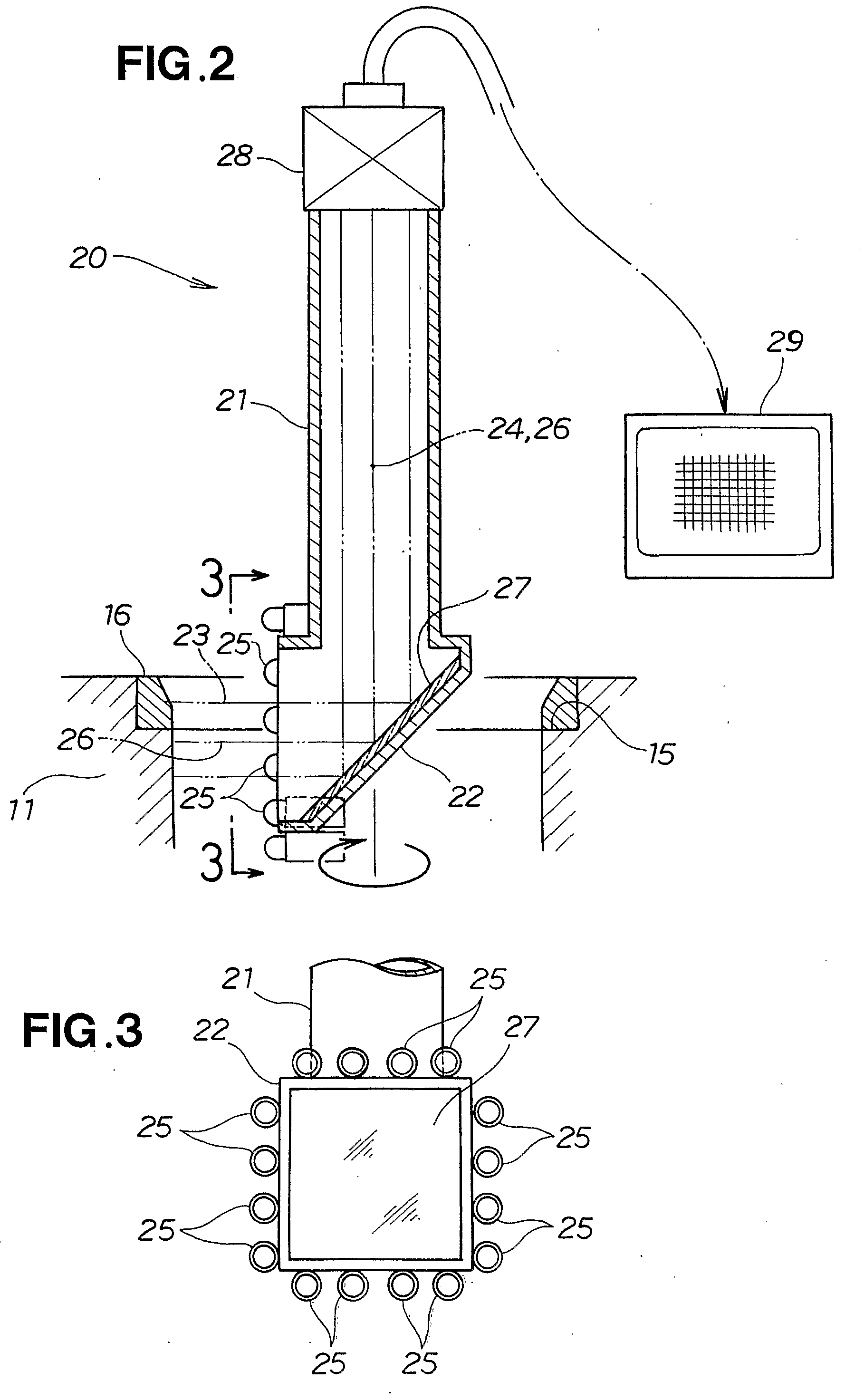
[0042]As shown in FIG. 2, the apparatus 20 for measuring gaps between attachment parts and valve seats is composed of a cylinder 21, a mirror accommodation chamber 22 that has a substantially triangular cross-section and is provided to one end (lower end in the Figure) of the cylinder 21, white light-emitting diodes 25 that are provided around the periphery of the mirror acc...


PUM


Abstract

An apparatus for measuring gaps that form between attachment parts (15) in exhaust ports. of an engine, and valve seats (16) provided to the attachment parts. This apparatus comprises, at one end of a cylinder (21), white light-emitting diodes (25) for emitting light orthogonal to a longitudinal axis (24) of the cylinder. An optical axis (26) from the light-emitting diodes is bent by 90° by a mirror (27). Color images obtained by a CCD camera (28) provided at the other end of the cylinder are binarized by a color image processor (29) with a range of hue, a range of chroma, and a range of brightness.

Description

TECHNICAL FIELD[0001]The present invention relates to a gap measurement apparatus for measuring gaps formed between valve seats and attachment parts after the attachment parts are formed in exhaust ports of an engine and the valve seats are press-fitted into these attachment parts. The invention also relates to a method for determining these gaps.BACKGROUND ART[0002]A cylinder head of an engine is provided with exhaust ports. These exhaust ports are opened and closed with air intake valves and air release valves. The members with which the air intake valves and air release valves are in direct contact are referred to as valve seats, and these valve seats must be durable. For example, structures are used in which steel valve seats are press-fitted into cylinder heads made from aluminum alloy castings.[0003]Specifically, seat-accommodating attachment parts (hereinafter referred to as “attachment parts”) are formed by cutting in the cylinder heads, and valve seats are press-fitted into...

Claims


Application Information

Patent Timeline
IPC IPC(8): G06K9/00
CPCF01L3/22F01L2103/00G01B11/14F01L2820/01F01L2820/02F01L2103/01F01L2303/01F01L2303/00
Inventor KANISAWA, MITSUHIROTSUBORAI, MITSUO
Owner HONDA MOTOR CO LTD
Why Eureka
Try Eureka