Outer pipe sleeve for a sea floor mooring pile

a technology of offshore petroleum structure and outer pipe sleeve, which is applied in the direction of vessel construction, transportation and packaging, foundation engineering, etc., can solve the problems of increasing the installation friction of the sleeve, and increasing the anchoring force of the pile. , to achieve the effect of reducing the friction of the installation of the sleeve and increasing the anchoring for

Inactive Publication Date: 2009-05-14
TECH FRANCE SA
View PDF14 Cites 25 Cited by
  • Summary
  • Abstract
  • Description
  • Claims
  • Application Information

AI Technical Summary

Benefits of technology

[0015]The present disclosure provides an improved system and method for increasing an anchoring force on a pile. The concepts regarding the pile can apply whether the pile capacity has been degraded and no longer able to support its intended load, or a load on the pile has increased to a level that may overstress the pile. A sleeve can be installed even in subsea conditions over the pile and can be used to provide an additional securing force to the existing pile. The sleeve may include its own padeye for coupling an anchor line or other coupling member to a structure to be secured. The sleeve may comprise a tubular sleeve or include an assembly of rings coupled together with at least one or more longitudinal members. An pile sleeve assembly with rings spaced a distance away from each other can help reduce the installation friction on the sleeve, as it is installed into the sea floor.

Problems solved by technology

At great depths, it may be problematic to use a pile-driving hammer or other equipment to install the pile.
Piles can become damaged, worn, or otherwise degraded.
Further, there are times in which an existing pile may be in a satisfactory condition, but may require to resist additional structural loads from a new design load case or change in design.
These new design load cases may overstress or be beyond the capacity of the existing pile.
However, the new solution still has the disadvantage of not providing full support until some later time, when the disturbed layers on the sea floor 4 can consolidate around the pile.

Method used


Image

  • Outer pipe sleeve for a sea floor mooring pile
  • Outer pipe sleeve for a sea floor mooring pile
  • Outer pipe sleeve for a sea floor mooring pile

Examples


Embodiment Construction

[0030]One or more illustrative embodiments of the concepts disclosed herein are presented below. For the sake of clarity, not all features of an actual implementation are described or shown in this application. It is understood that in the development of an actual embodiment, numerous implementation-specific decisions must be made to achieve the developer's goals, such as compliance with system-related, business-related and other constraints, which vary by implementation and from time to time. While a developer's efforts might be complex and time-consuming, such efforts would be, nevertheless, a routine undertaking for those of ordinary skill in the art having benefit of this disclosure.

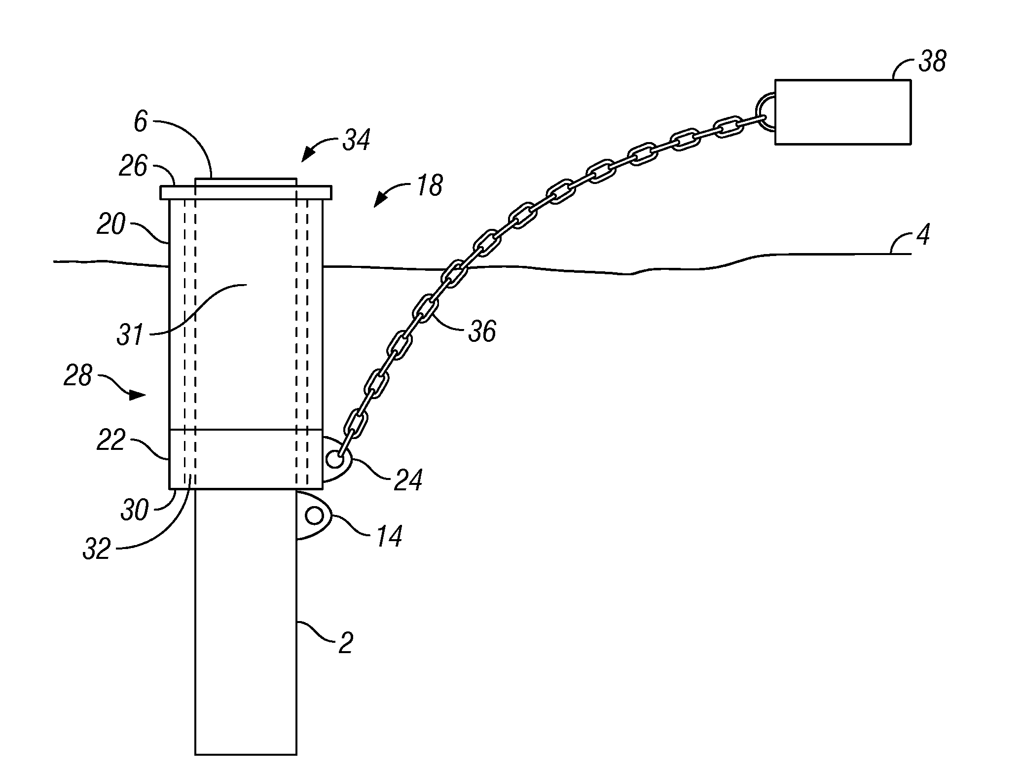
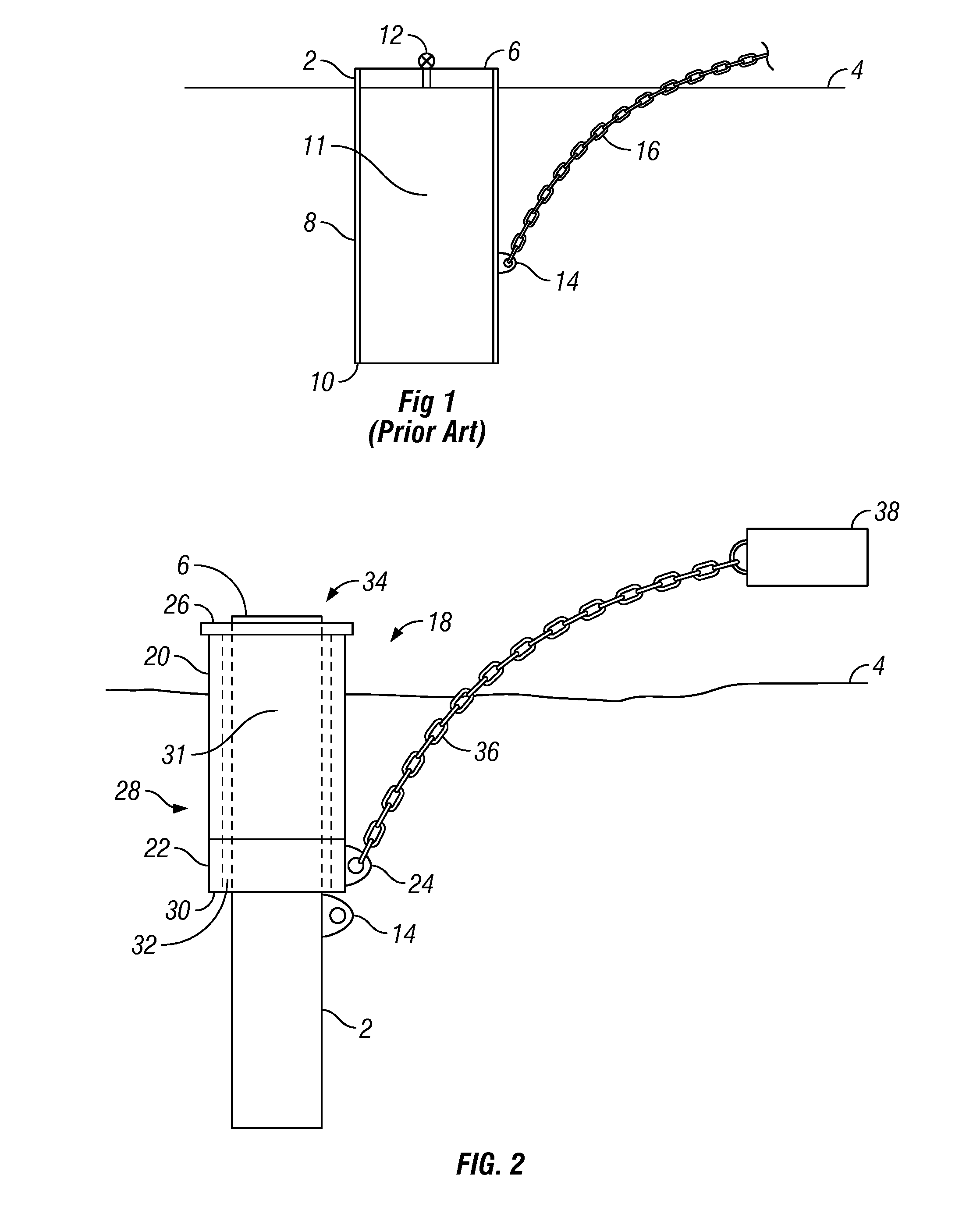
[0031]FIG. 2 is a cross-sectional schematic diagram of a system for supporting a pile installed in a sea floor. The pile 2, having a padeye 14, is installed at least partially in a sea floor 4. Due to degraded conditions, additional loading, or other circumstances, the pile 2 may not be suitable for ...


PUM


Abstract

The present disclosure provides an improved system and method for increasing an anchoring force on a pile. The concepts regarding the pile can apply whether the pile is degraded and no longer able to support its intended load, or a load on the pile has increased to a level that may overstress the pile. A sleeve can be installed even in subsea conditions over the pile and can be used to provide an additional securing force to the existing pile. The sleeve may include its own padeye for coupling an anchor line or other coupling member to a structure to be secured. The sleeve may also include an assembly of rings coupled together with at least one longitudinal member. The assembly with the rings spaced a distance away from each other may help reduce an installation friction on the sleeve, as it is installed into the sea floor.

Description

CROSS REFERENCE TO RELATED APPLICATIONS[0001]Not applicable.STATEMENT REGARDING FEDERALLY SPONSORED RESEARCH OR DEVELOPMENT[0002]Not applicable.NAMES OF PARTIES TO A JOINT RESEARCH AGREEMENT[0003]Not applicable.REFERENCE TO APPENDIX[0004]Not applicable.BACKGROUND[0005]1. Field[0006]The disclosure relates to pile anchor systems and methods, and particularly to pile anchor systems and methods for offshore petroleum structures, such as floating structures, drilling or production risers, and other marine structures.[0007]2. Description of Related Art[0008]Often marine structures used in offshore petroleum industry are moored to a pile that is anchored to a sea floor. The pile is generally a tubular element that is installed into seabed deposits that form the sea floor. Depending on the depth of the sea at a given location, various methods can be used to install the pile into the sea floor. At great depths, it may be problematic to use a pile-driving hammer or other equipment to install ...

Claims


Application Information

Patent Timeline
Patent Type & Authority Applications(United States)
IPC IPC(8): E02D5/00
CPCB63B21/27E21B7/20B63B21/50
Inventor MACONOCHIE, ALASDAIROLIPHANT, JOHNTHOMAS, PIERRE-ARMAND
Owner TECH FRANCE SA
Why Eureka
Try Eureka