Stabilizing Strip Intended for Use in Reinforced Earth Structures

a technology of stabilizing strips and reinforced earth structures, which is applied in the direction of bulkheads/piles, soil preservation, artificial islands, etc., can solve the problems of difficult deviation of stabilizing strips, interference with the positioning of stabilizing strips, and difficulty in making such strips difficult to devia

Inactive Publication Date: 2009-05-14
TERRE ARMEE INT
View PDF10 Cites 10 Cited by
  • Summary
  • Abstract
  • Description
  • Claims
  • Application Information

AI Technical Summary

Benefits of technology

[0017]The invention thus proposes a stabilizing strip intended to be used in reinforced earth structures comprising n

Problems solved by technology

The use of such stabilizing strips in reinforced earth structures can present difficulties, in particular when obstacles are present in the structure.
For example, the presence of verti

Method used


Image

  • Stabilizing Strip Intended for Use in Reinforced Earth Structures
  • Stabilizing Strip Intended for Use in Reinforced Earth Structures
  • Stabilizing Strip Intended for Use in Reinforced Earth Structures

Examples


Embodiment Construction

[0043]For reasons of clarity, the various components shown in the Figures are not necessarily to scale.

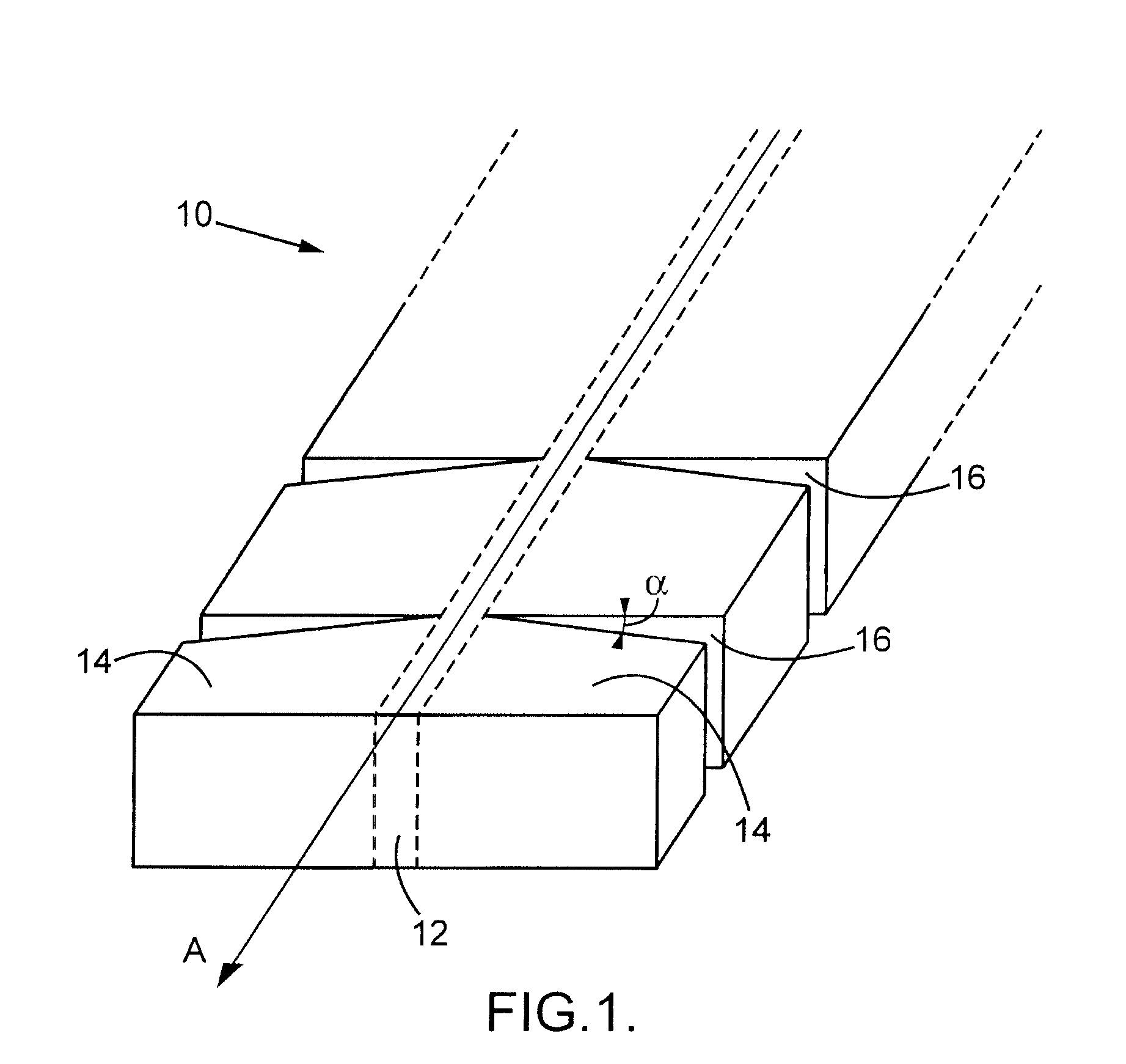
[0044]By “longitudinal” is understood the direction along the longitudinal axis of the strip, the “lateral” direction being a direction approximately perpendicular to the longitudinal direction.

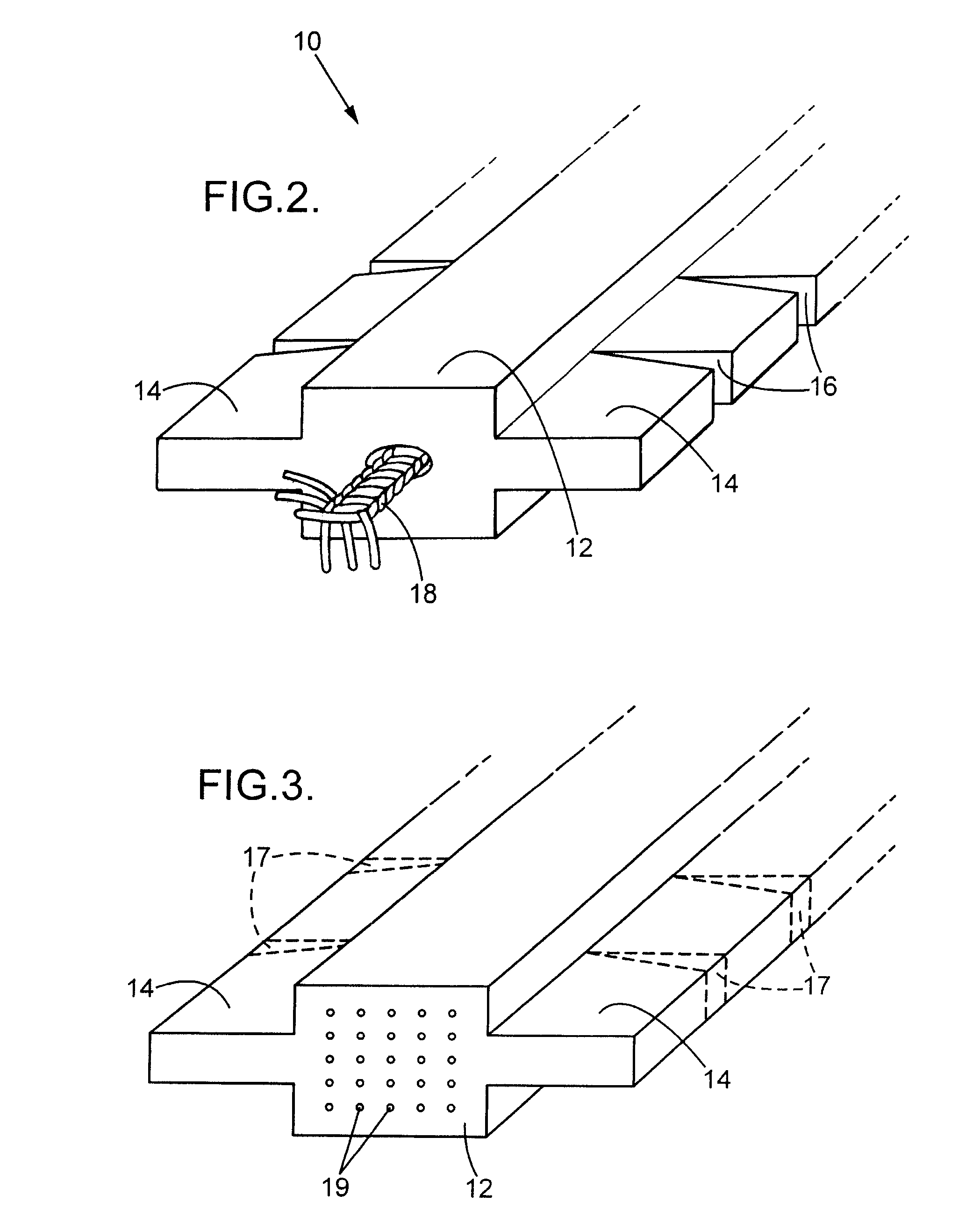
[0045]By “cord” is meant an assembly, obtained by twisting or plaiting, of at least three fibres made up of a plurality of strands of yarn, for example at least three strands of yarn, made from textile, synthetic, plastic or metal materials or a combination of these different fibres or yarns.

[0046]The cords chosen can for example be narrow, with a diameter in the region of one millimetre, or thicker, with a diameter in the region of one centimetre.

[0047]In the meaning of the invention, “pre-notch” denotes a part of the stabilizing strip which is prepared in order to be notched so as to form a laterally-opening notch. The pre-notch can be opened up in order to obtain the laterally-opening not...


PUM


Abstract

Stabilizing strip (10) intended for use in reinforced earth structures comprising laterally-opening notches (16) and/or pre-notches (17) making it possible to impose a finite radius of curvature on said strip (10).

Description

BACKGROUND OF THE INVENTION[0001]The present invention relates to a stabilizing strip intended for use in reinforced earth or strengthened soil structures, together with the use of such a strip for the construction of reinforced earth or strengthened soil structures.[0002]A reinforced earth structure combines compacted backfill, a facing and reinforcements that are connected or not to the facing.[0003]Various types of reinforcements can be used: metal reinforcements, for example galvanized steel rods, or flexible stabilizing strips, for example polyester fibre-based. They are implanted in the earth at a density dependant on the stresses which may be exerted on the structure. Mention can be made for example of the thrust stresses of the ground which are taken up by the friction between the earth and the reinforcements.[0004]The facing is usually made from precast concrete elements in the form of slabs or blocks, juxtaposed to cover the front surface of the structure.[0005]In certain ...

Claims


Application Information

Patent Timeline
IPC IPC(8): E02D3/00
CPCE02D29/0241
Inventor MORIZOT, JEAN CLAUDEFREITAG, NICOLAS
Owner TERRE ARMEE INT
Why Eureka
Try Eureka