

Shape-changing anatomical anchor
a technology of anatomical anchors and screws, applied in the field of fixation devices, can solve the problems of adding additional steps and expense to the surgical procedure, affecting the natural bone structure of the patient, and affecting the effect of the surgical procedure,
- Summary
- Abstract
- Description
- Claims
- Application Information
AI Technical Summary
Benefits of technology
Problems solved by technology
Method used
Image

Examples
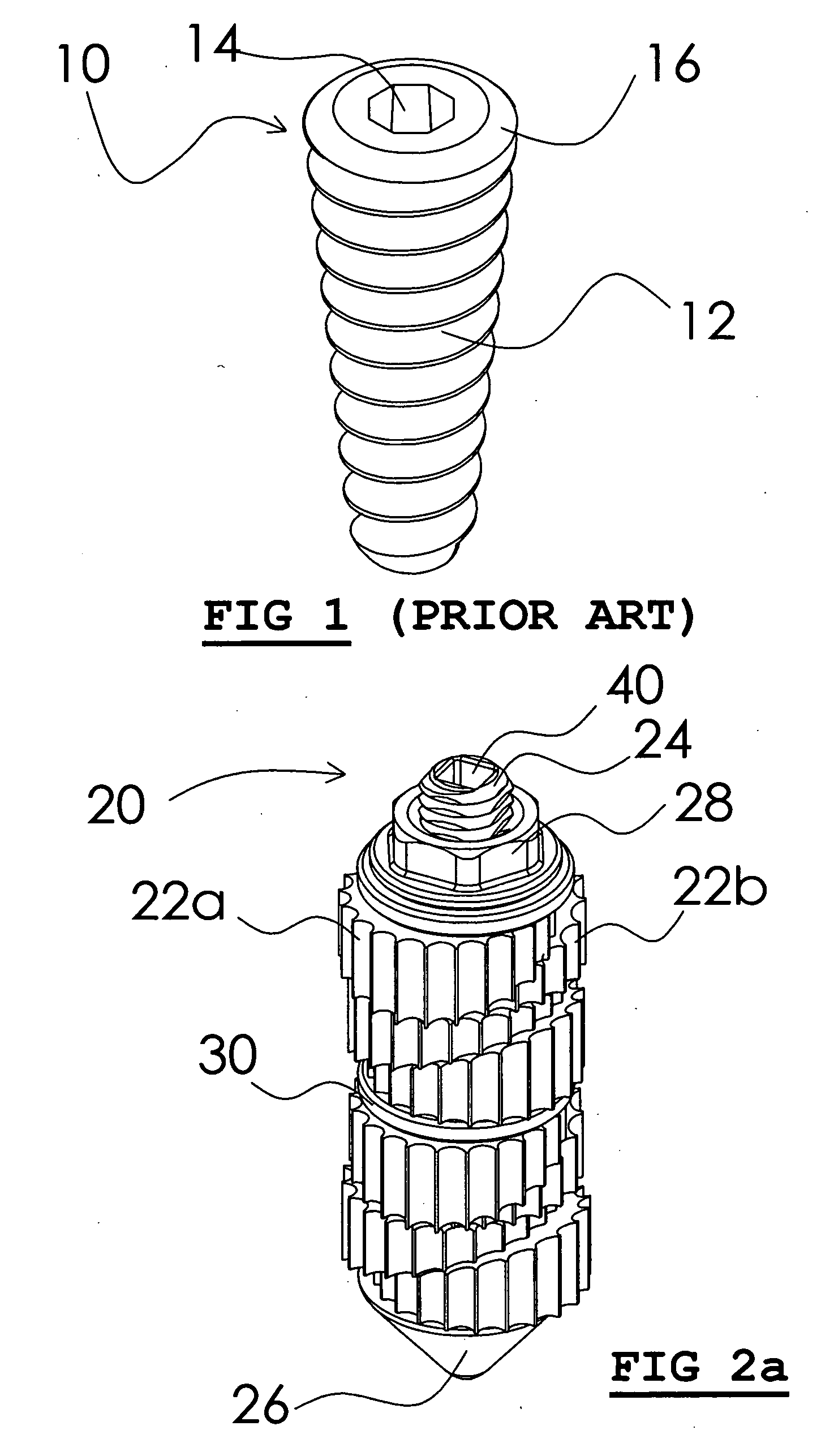
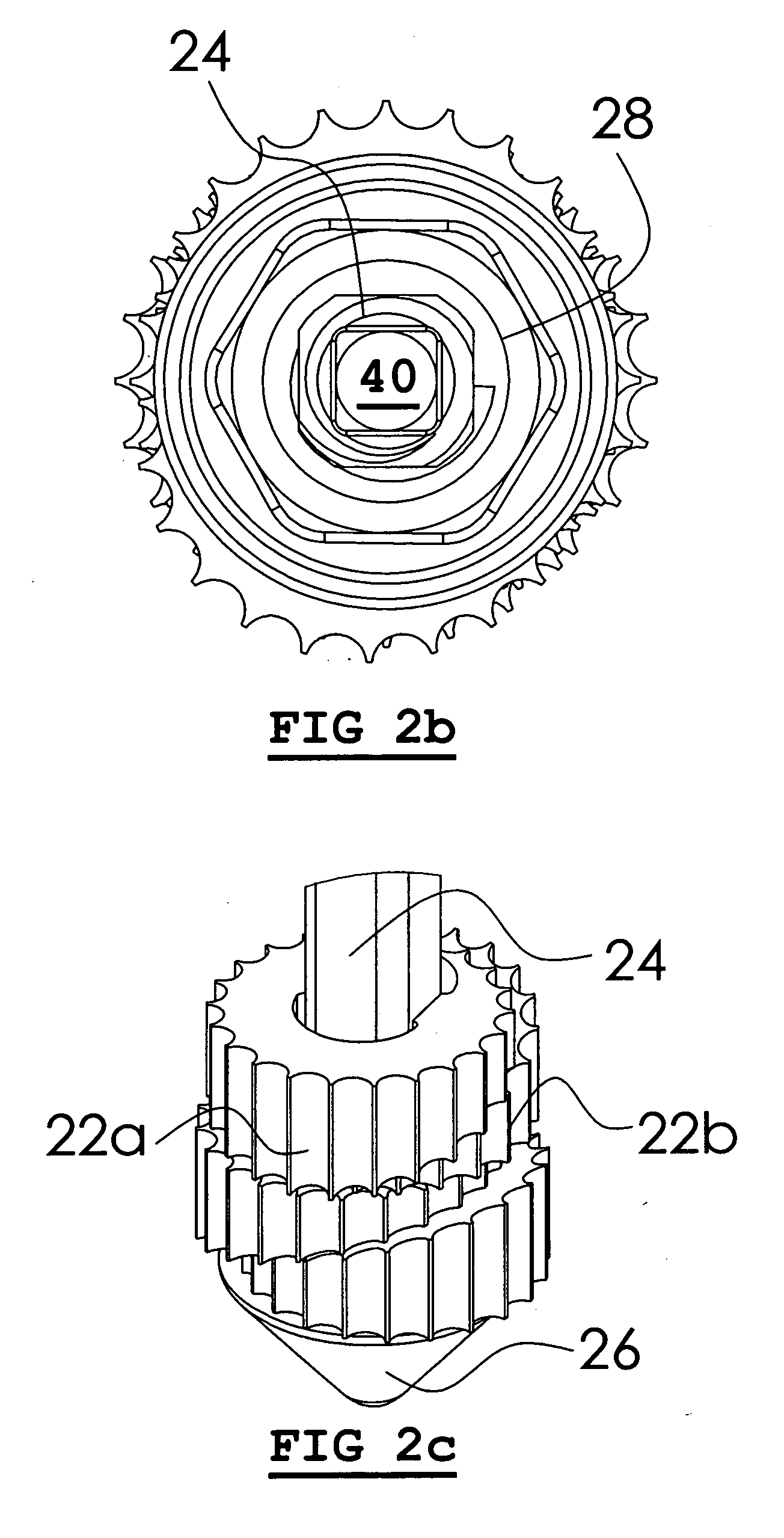
embodiment 20
[0036]One possible embodiment 20 is shown in FIG. 2a-2c. In this implementation, the anchor's members comprise at least one pair of wedge-shaped body portions 22a, 22b; four such pairs are shown in FIG. 2a, though more or fewer pairs may be used as needed for a given application.
[0037]Each wedge-shaped body portion has at least one sloped surface, with a sloped surface of one body portion of each pair stacked atop a sloped surface of the other body portion of each pair, such that the pair of wedge-shaped body portions tends to slide along their sloped surfaces in opposite directions when subjected to a force applied substantially perpendicular to the directions of movement. Thus, as oriented in FIG. 2a, body portions 22a and 22b slide to the left and right, respectively, in response to a force applied vertically.
[0038]The activation means includes a central shaft 24 that runs through each of the wedge-shaped body portions. The activation force is then applied along an axis parallel ...
embodiment 80
[0052]Another possible piloted embodiment 80 is shown in FIGS. 6a-6j. This anchor's body design has a blunt tip, which is primarily due to the desire to provide an anchor with a very high surface area and having very high tissue retention, without causing tissue damage during or after anchor installation. The basic principles remain the same: insert anchor into pilot hole, and activate the anchor to generate tissue retention forces.
[0053]An assembled anchor is shown in FIG. 6a. The anchor's members comprise at least two body portions: a back portion 82 (shown in detail in FIG. 6b) and a front portion 84 (shown in detail in FIG. 6c), which are arranged to be nested and interlocked such that the distance each body portion can travel radially away from the anchor's activation means when the anchor is activated is limited by the other body portions. In this example, key features 86 on body portion 84 are arranged to fit within slot features 88 on body portion 82 when the anchor is assem...
PUM
 Abstract
Description
Claims
Application Information