Intraventricular electrodes for electrical stimulation of the brain

a technology of electrical stimulation and intraventricular electrodes, which is applied in the direction of internal electrodes, head electrodes, therapy, etc., can solve the problems of increased risks in the implementation of dbs, limited effectiveness of emcs, and inability to achieve the effect of reducing or eliminating side effects, causing intolerable tonic contraction of the patient's muscles, and reducing the effect of side effects

Inactive Publication Date: 2009-05-14
WISCONSIN ALUMNI RES FOUND
View PDF18 Cites 34 Cited by
  • Summary
  • Abstract
  • Description
  • Claims
  • Application Information

AI Technical Summary

Benefits of technology

[0010]Arrangements of this nature may be used in combination with a DBS electrode, e.g., to correct the use of a previously-implanted DBS electrode which is not providing the desired effect. As an example, the lead 150 of FIG. 1B might be implanted so that the current sources 152 and sinks 154 are at or near the subthalamic nucleus (as desired), but if implanted too near the internal capsule, some of the current may “bleed over” to the internal capsule and cause intolerable tonic contraction of the patient's muscles. As a result, the patient may prefer to simply leave the DBS lead 150 inactive. FIG. 2B then illustrates the use of a ventricular electrode to “salvage” the use of an implanted DBS lead 250. Here, a lead 262 similar to the lead 206 of FIG. 2A is installed in the brain 16 with its current sink 264 situated within the ventricle 18, thereby effectively converting the entire ventricle 18 into a current sink. The current sink 264 is connected to the positive terminal of the power supply 260 in lieu of the current sink 254 of the DBS lead 250, with only the current source(s) 252 of the lead 250 being active. As a result, current supplied to the current source(s) 252 flows toward the ventricle 18, and to the current sink 264 therein, thereby attracting the emitted current to the ventricle 18 in a medial direction, and away from the internal capsule, so that side effects are reduced or eliminated. In similar respects, the intraventricular current sink 202 of FIG. 2A might be installed to adapt the performance of an ineffective extradural current sink 102 as in FIG. 1A.

Problems solved by technology

However, the effectiveness of EMCS is limited, possibly because the emitted current can only stimulate portions of the cortex 16 near the cranium 12 owing to the extradural locations of the current source 100 and current sink 102.
In this respect, it is believed that effectiveness of EMCS is also limited because at least a portion of the current is shunted from the current source 100 to the current sink 102 by the conductive cerebrospinal fluid in the subarachnoid space 14, with only a limited amount of current entering the cortex 16.
DBS can be highly effective, but since the installation of the lead 150 is more invasive, the implementation of DBS bears greater risks (such as the risk of hemorrhaging caused by insertion of the lead 150).
Additionally, the effectiveness of DBS can decrease, and / or adverse side effects can arise, if the lead 150 is not ideally situated.

Method used


Image

  • Intraventricular electrodes for electrical stimulation of the brain
  • Intraventricular electrodes for electrical stimulation of the brain
  • Intraventricular electrodes for electrical stimulation of the brain

Examples


Embodiment Construction

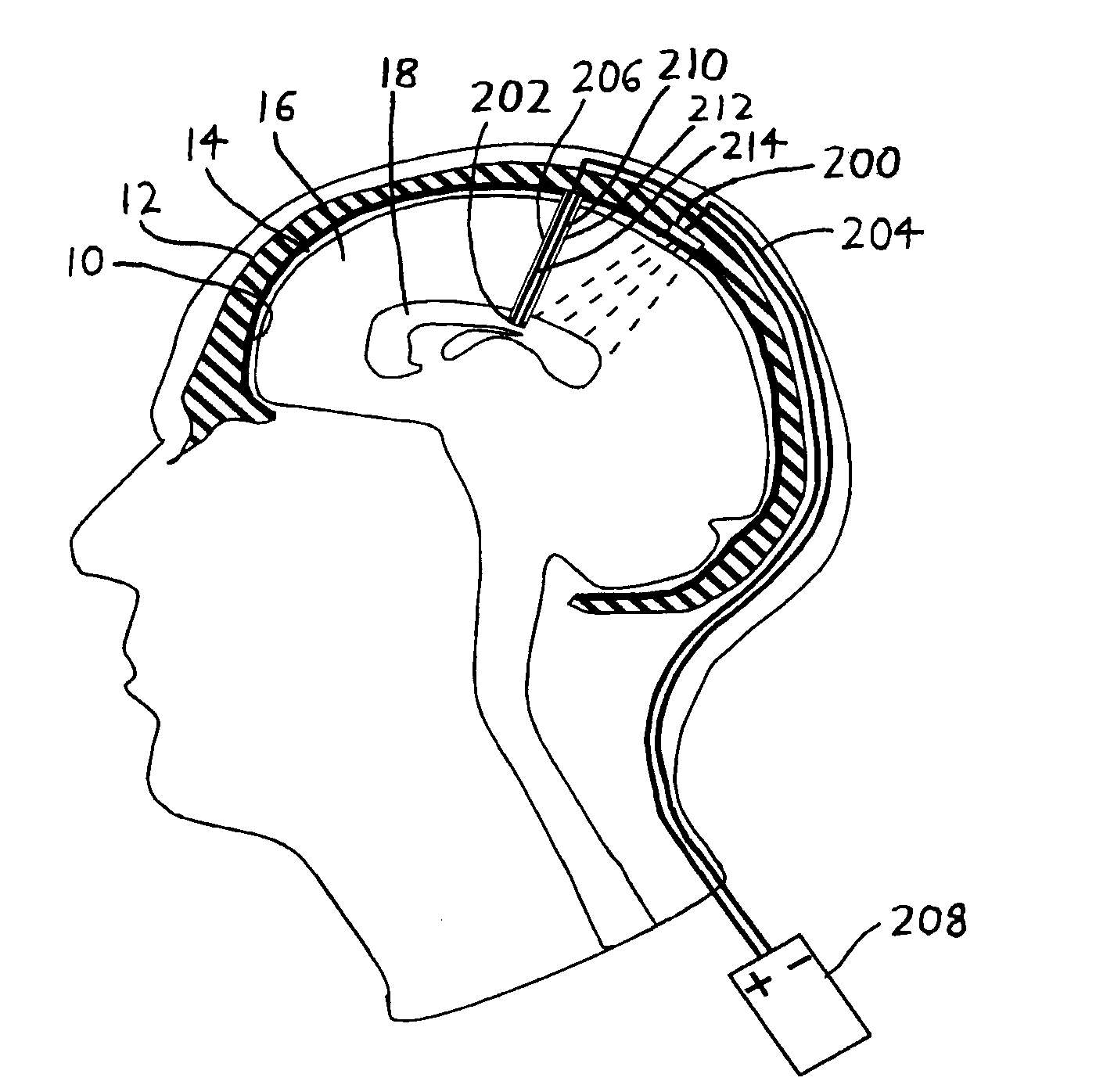
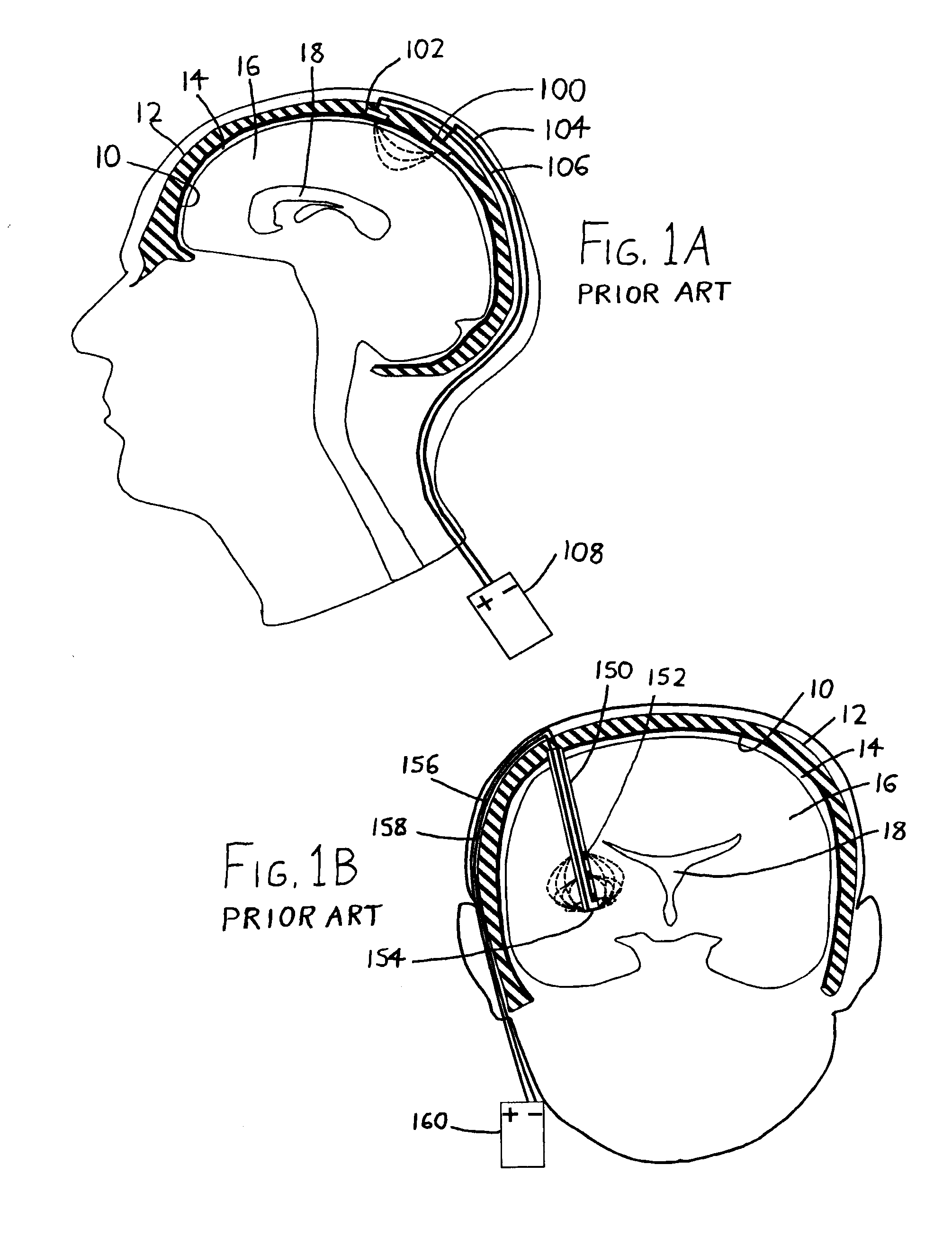
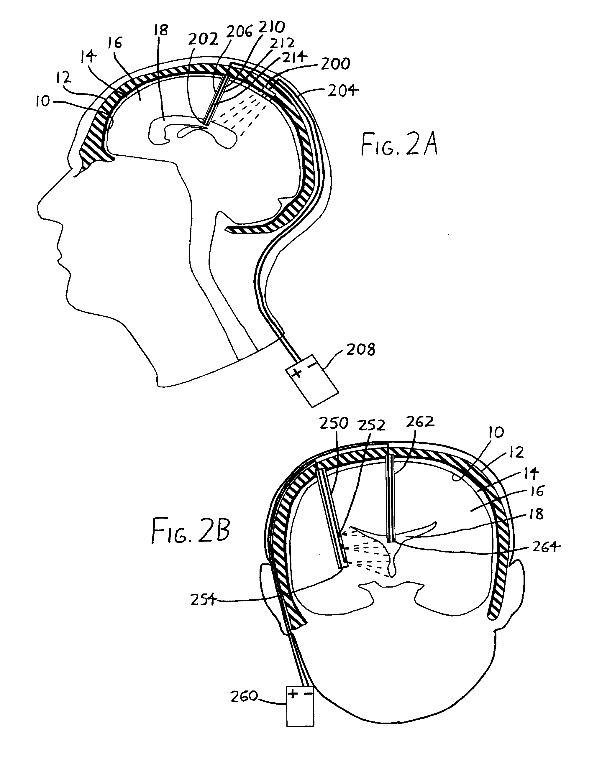
[0016]To elaborate on the discussion in the Summary above, the invention may be implemented instead of preexisting brain stimulation systems, or it may be implemented alongside them. As an example, in FIG. 2B, the ventricular current sink 264 might be used in addition to the current sink 254, rather than instead of it. In this case, the current sinks 254 and 264 might operate in tandem (e.g., with both being connected to the positive terminal of the power supply 260), or one might be operated differently than the other (e.g., they could be connected to separate terminals which operate them at different voltages, frequencies, etc. so that current flow between the current source 252 and the sink 254 differs from that between the source 252 and the sink 264). In similar respects, the arrangement of FIG. 2A might utilize an extradural current sink (as in FIG. 1A) in addition to the intraventricular current sink 202. It is also possible to provide the current source(s) and current sink(s...


PUM


Abstract

An electrode—preferably an anode (current sink)—is implanted within a ventricle of the brain so that the cerebrospinal fluid therein, which is highly conductive, effectively makes the ventricle a conductive extension of the anode. An opposing electrode (i.e., a cathode) can then be situated within or outside the brain (e.g., extradurally) so that a portion of the brain to be electrically stimulated is situated between the electrodes. The electrodes can then be energized at appropriate frequencies and current / voltage levels to apply the desired stimulation, in a manner similar to preexisting Deep Brain Stimulation (DBS), Extradural Motor Cortex Stimulation (EMCS), and other electrical brain stimulation procedures.

Description

FIELD OF THE INVENTION[0001]This document concerns an invention relating generally to methods and devices for electrical stimulation of the brain.BACKGROUND OF THE INVENTION[0002]Electrical stimulation of the brain is being studied for the treatment of a wide variety of neurological and psychiatric conditions. An example of a first arrangement, known as Extradural Motor Cortex Stimulation (EMCS), is illustrated in simplified form in FIG. 1A. Here, a current source (i.e., a cathode) 100 is situated extradurally (i.e., atop or outside the dura mater 10), with a nearby current sink (i.e., an anode) 102 also being extradurally situated nearby. Respective leads 104 and 106 extend from each of the current source 100 and current sink 102 through the skull 12, usually through a burr cap (not shown), i.e., a “plug” inserted through a hole cut in the skull 12. The leads 104 and 106 are then usually run subcutaneously down the skull 12 and neck to a power supply 108, e.g., a neurostimulator su...

Claims


Application Information

Patent Timeline
IPC IPC(8): A61N1/05
CPCA61N1/0534A61N1/0531
Inventor MONTGOMERY, JR., ERWIN B.
Owner WISCONSIN ALUMNI RES FOUND
Why Eureka
Try Eureka