Oil strainer for transmission

a technology of oil strainer and transmission tube, which is applied in the direction of filtration separation, lubricant mounting/connection, and separation process, etc., can solve the problems of affecting the aeration effect of the upper case and the lower case, so as to reduce the total amount of oil and reduce the structure. simple, the effect of restrainting the aeration

Inactive Publication Date: 2009-05-21
HONDA MOTOR CO LTD
View PDF20 Cites 19 Cited by
  • Summary
  • Abstract
  • Description
  • Claims
  • Application Information

AI Technical Summary

Benefits of technology

[0010]Accordingly, it is an object of the present invention to provide an oil strainer for a transmission which is simple

Problems solved by technology

In the oil strainer disclosed in Japanese Patent Laid-open No. 2001-124188, complete removal of the rib formed along the whole circumference of the flange constituting the joint part between the upper case and the lower case is difficult in view of vibration welding of the cases, so that the site for forming the notch is restricted.
Therefore, there remains the problem of, for example, stagnation of air at the four corners of the oil strainer, and fine aeration possibly caused by the stagnating air.
Therefore, it is difficult to secure an aeration balance in each cases of forward running and rearward running.
In addition, in view of the structure in which a main oil passage to the oil suction port of the strainer is along the forward vehicle running direction, the system in which the strainer is inclined along the front-rear direction leaves some air stagnation area in the oil passage, again causing the fine aeration.
Therefore, when the total amount of the oil in t

Method used


Image

  • Oil strainer for transmission
  • Oil strainer for transmission
  • Oil strainer for transmission

Examples


Embodiment Construction

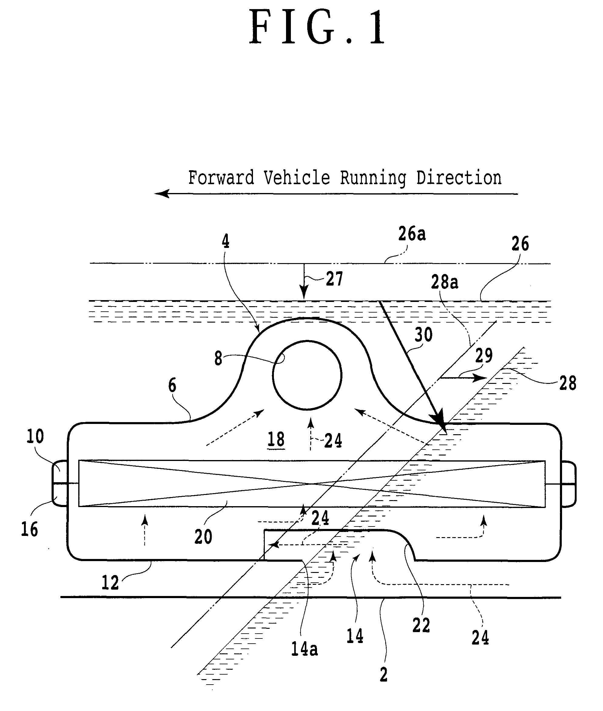
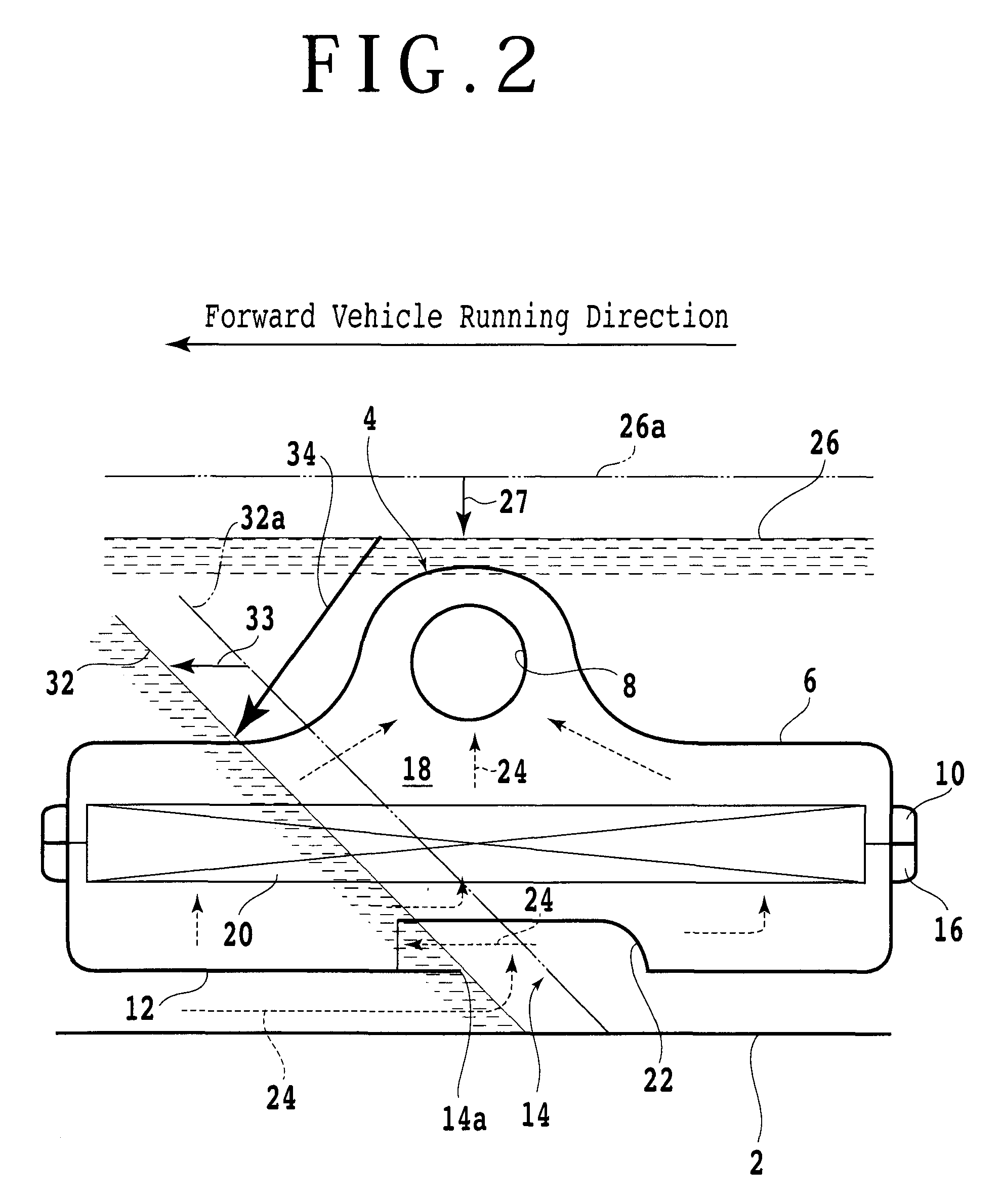
[0030]Now, an oil strainer for a transmission according to an embodiment of the present invention will be described in detail below, referring to the drawings. Referring to FIG. 1, a schematic sectional view of the oil strainer according to one embodiment of the present invention is shown, together with changes of an oil surface at the time of standstill of the vehicle and at the time of an acceleration of the vehicle.

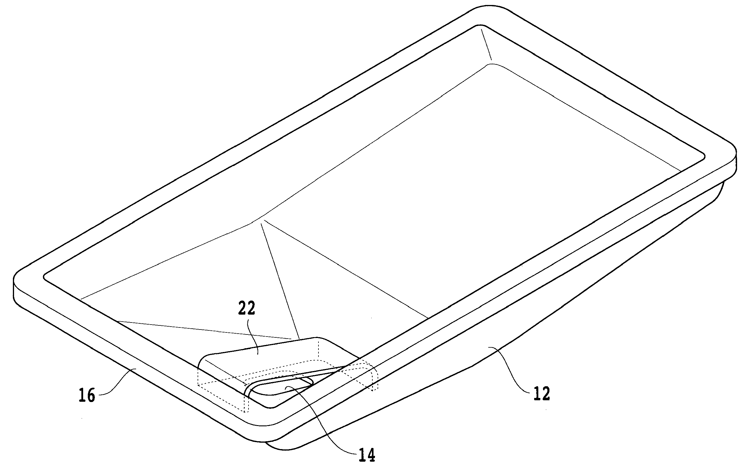
[0031]Reference numeral 2 denotes a bottom surface of a transmission case, and the oil strainer 4 is disposed in the transmission case. The oil strainer 4 includes an upper case 6 provided with a communication port 8 for communication with an oil pump in a side surface of an upper part thereof, a lower case 12 which is provided with an oil suction port 14 in its lower surface and which is joined to the upper case 6, and a filter member 20 which is disposed in a space 18 formed by joining the upper and lower cases 6 and 12 and which is provided for filtering an oil flow...


PUM

PropertyMeasurementUnit
Timeaaaaaaaaaa
Accelerationaaaaaaaaaa

Abstract

An oil strainer for a transmission including a resin-made upper case which is formed in a side surface of an upper part of a communication port for communication with a pump and which has an upper flange along the outer periphery thereof, a resin-made lower case which is provided with an oil suction port in a lower surface thereof and which has a lower flange joined to the upper flange of the upper case, and a filter member which is disposed in a space formed by joining the upper and lower cases and which filters an oil flowing from the oil suction port to the communication port. The oil strainer is configured to further includes an oil suction port cover member which is so formed as to cover at least an inside upper surface of the oil suction port and which forms a passage for conducting the oil to the filter member.

Description

[0001]This is a continuation of International PCT Application NO. PCT / JP2007 / 057235, filed Mar. 30, 2007, which was not published in English.BACKGROUND OF THE INVENTION[0002]1. Field of the Invention[0003]The present invention relates to an oil strainer for filtering an oil in a transmission case.[0004]2. Description of the Related Art[0005]An oil used as a working fluid or a lubricating oil in a transmission is reserved in a lower part of a transmission casing, is sucked by an oil pump and is supplied to a control valve and other parts to be lubricated. In this case, it is a common practice to disposed an oil strainer in the lower part of the transmission casing and to filter the oil through the strainer before the oil is sucked by the pump. A configuration in which a filter member formed from a non-woven fabric or the like is disposed in a resin-made case to form the oil strainer has been known. In this case, the filter member composed of the non-woven fabric is clamped between an...

Claims


Application Information

Patent Timeline
IPC IPC(8): F01M11/03F16H57/04
CPCB01D35/0273F16H57/0452F16H57/0443F16H57/0404
Inventor SHINBORI, ISAMUTSUBATA, YOSHIMICHITAKEI, SUSUMUTAKEI, YASUYUKI
Owner HONDA MOTOR CO LTD
Why Eureka
Try Eureka