
Electronically keyed dispensing systems and related methods utilizing near field frequency response

a technology of electronic keying and dispensers, applied in the field of electronic keying fluid dispensing systems, can solve the problems of preventing the manufacturer from obtaining an adequate financial return on the dispensers, affecting the dispensing of hand moisturizing lotion to hospital personnel, and difficult service, etc., to achieve the effect of convenient dispensing of a quantity

Active Publication Date: 2009-05-21
KANFER JOSEPH
View PDF16 Cites 36 Cited by
  • Summary
  • Abstract
  • Description
  • Claims
  • Application Information

AI Technical Summary

Benefits of technology

The present invention provides electronically keyed dispensing systems and related methods utilizing near field frequency response. The invention includes a refill container with an identifier having one of a selected number of electronic signatures. The invention also includes a dispensing system with a housing and an operational mechanism, and a controller in communication with the emitting and receiving devices. The invention also includes a container carrying dispensable material with a dispensing interface and an identifier with one of a selected number of electronic signatures. The technical effects of the invention include improved security, efficiency, and accuracy in dispensing materials.

Problems solved by technology

Dispensers may directly hold a quantity of fluid, but these have been found to be messy and difficult to service.
For example, it would be very upsetting to hospital personnel to have hand moisturizing lotion dispensed when they instead desire anti-bacterial soap.
Such activity prevents the manufacturer from obtaining an adequate financial return on the dispensers which are typically sold at cost or less.
Although mechanical keys are helpful in ensuring that the proper refill bag is installed into the proper dispenser and that the distributors maintain their business clientele, these keying systems have been found to be lacking.
For example, if a distributor's competitor cannot install their refill packages into the distributor's dispenser device, the competitor may remove or alter the keying mechanism.
As such, inferior fluid may be installed into a particular dispenser and the preferred distributor will lose sales.
Mechanical keying also necessitates significant tooling costs underwritten by the manufacturer to design special nozzles and dispensers that are compatible with one another.
Accordingly, the inventory costs for maintaining refill bags with a particular key is significant.
And the lead time for manufacturing such a refill bag may be quite lengthy.
Moreover, the particular identification of a particular keying device may be lost or damaged so that it is difficult to determine which type of keying configuration is needed for the refill bags.
Although effective in its' stated purpose, the device disclosed in the patent is lacking in that a specific orientation is required for installation of the refill container.
It is believed that this scheme is lacking in that it provides no teaching for adaptability for use with multiple dispensers.
It is also believed that the disclosed configuration is subject to a mis-alignment of the coils which may lead to mis-identification of the bag.
And the use of a single coil as the emitting and receiving coils may lead to mis-identification of the bag.

Method used


Image

  • Electronically keyed dispensing systems and related methods utilizing near field frequency response
  • Electronically keyed dispensing systems and related methods utilizing near field frequency response
  • Electronically keyed dispensing systems and related methods utilizing near field frequency response

Examples


Embodiment Construction

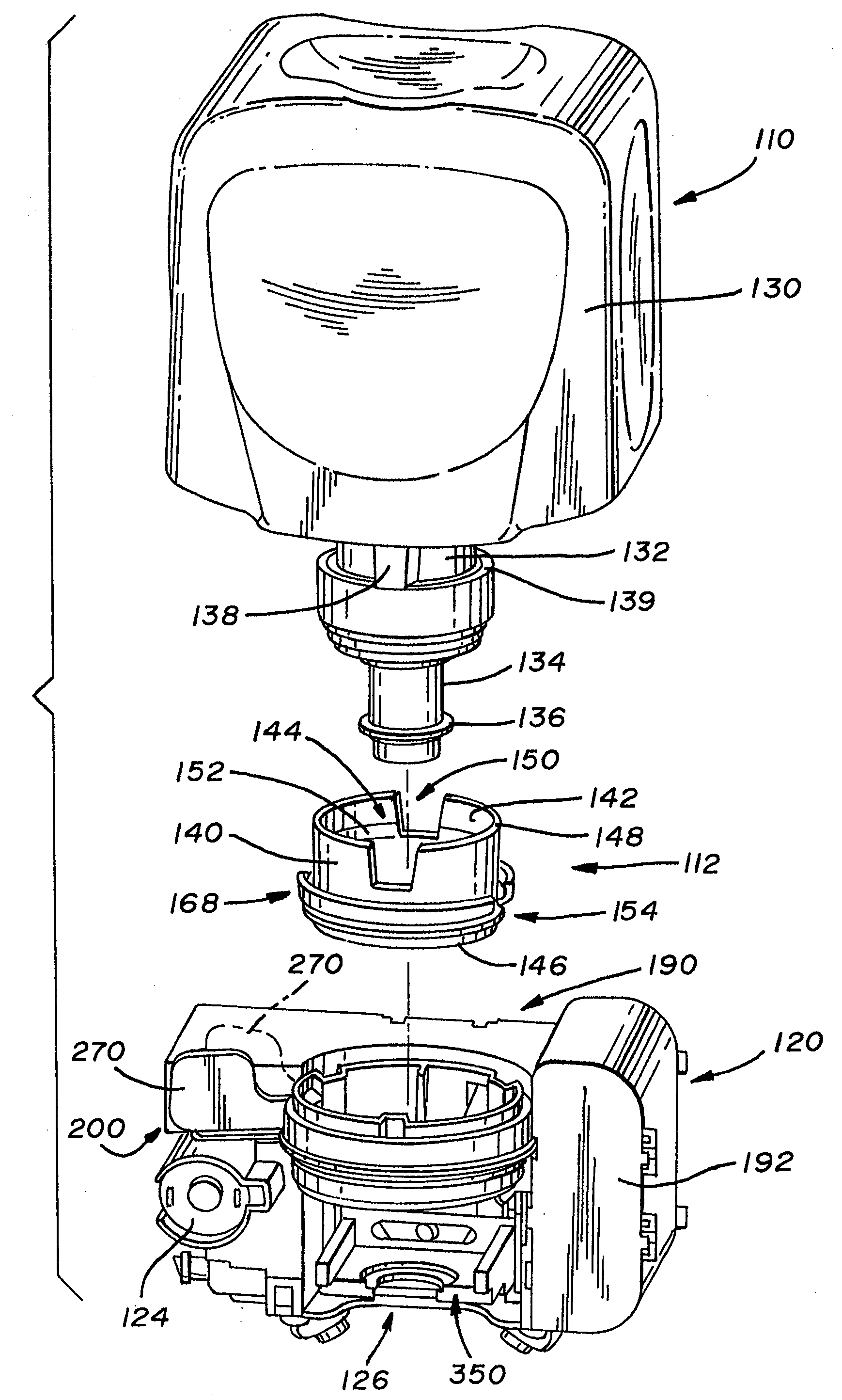
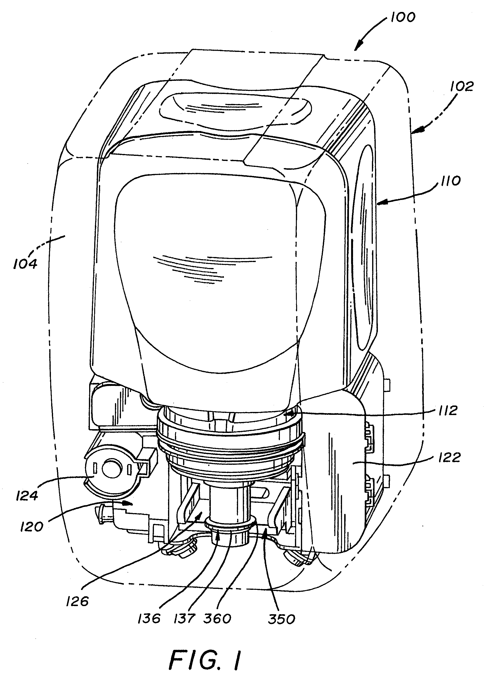
[0038]It will be appreciated from a reading of the Background Art that a primary need for dispensing systems is the ability to prevent “stuffing” of competitor's refill containers in a manufacturer's dispenser or in dispensers serviced by a distributor authorized by the manufacturer. The exemplary system disclosed herein fills this need by facilitating sharing of data between a communication device associated with the refill container and a communication device associated with the dispenser housing. Sharing of data includes, but is not limited to: the type of material within a refill container; a refill container's identification code; a concentration ratio within the refill container; a distributor's identification code; quality control information, such as manufacture dates and lot size; pump and / or nozzle size; the type of pump actuating mechanism associated with a dispenser; the type of dispenser location, such as a restaurant, hospital school, factory, etc.; the dispenser's his...


PUM

PropertyMeasurementUnit
frequenciesaaaaaaaaaa
period of timeaaaaaaaaaa
timeaaaaaaaaaa

Abstract

A dispensing system is disclosed which utilizes an electronically powered key device and / or identification code associated with a refill container to preclude the need for mechanical keys. The system utilizes a near field frequency response to determine whether a refill container is compatible with a dispensing system. In particular, the refill container is provided with a coil terminated by one of a number of capacitors. The container is received in a housing that provides a pair of coils that are in a spatial relationship with the installed refill container's coil. By energizing one of the housing's coils, the other coil detects a unique electronic signature generated by the container's coil. If the signature is acceptable, the dispensing system is allowed to dispense a quantity of material. The system also provides a unique latching mechanism to retain the container and ensure positioning of all the coils.

Description

CROSS REFERENCE TO RELATED APPLICATION[0001]This is a divisional application of application Ser. No. 11 / 013,727 filed Dec. 15, 2004, which is incorporated herein by reference.TECHNICAL FIELD[0002]The present invention is generally directed to dispensing systems. In particular, the present invention is directed to keyed dispensers which allow only designated refill containers with dispensable material to be installed therein and, if desired, installed by selected distributors. More specifically, the present invention is directed to electronically keyed fluid dispensing systems.BACKGROUND ART[0003]It is well known to provide fluid dispensers for use in restaurants, factories, hospitals, bathrooms and the home. These dispensers may contain fluids such as soap, anti-bacterial cleansers, disinfectants, lotions and the like. It is also known to provide dispensers with some type of pump actuation mechanism wherein the user pushes or pulls a lever to dispense a quantity of fluid into the us...

Claims


Application Information

Patent Timeline
Patent Type & Authority Applications(United States)
IPC IPC(8): B67D5/06B67D5/64G01F11/00B67D7/06B67D7/08B67D7/10B67D7/22B67D7/34B67D7/56B67D7/84
CPCB41J2/17546B67D7/348B41J2/17506A47K5/1217Y10T29/49826B67D2001/0811G07F7/00
Inventor REYNOLDS, AARON R.ROSENKRANZ, MARK E.WATERHOUSE, PAUL
Owner KANFER JOSEPH
Learn More