
Fluid handling device with isolating chamber
a technology of flue gas and isolating chamber, which is applied in the direction of valve operating means/releasing devices, instruments, pressure difference measurement between multiple valves, etc., can solve the problems of avoid undesirable signal bias and noise, and avoid regions of stagnant fluid , the effect of facilitating bacterial growth
- Summary
- Abstract
- Description
- Claims
- Application Information
AI Technical Summary
Benefits of technology
Problems solved by technology
Method used
Image


Examples
Embodiment Construction
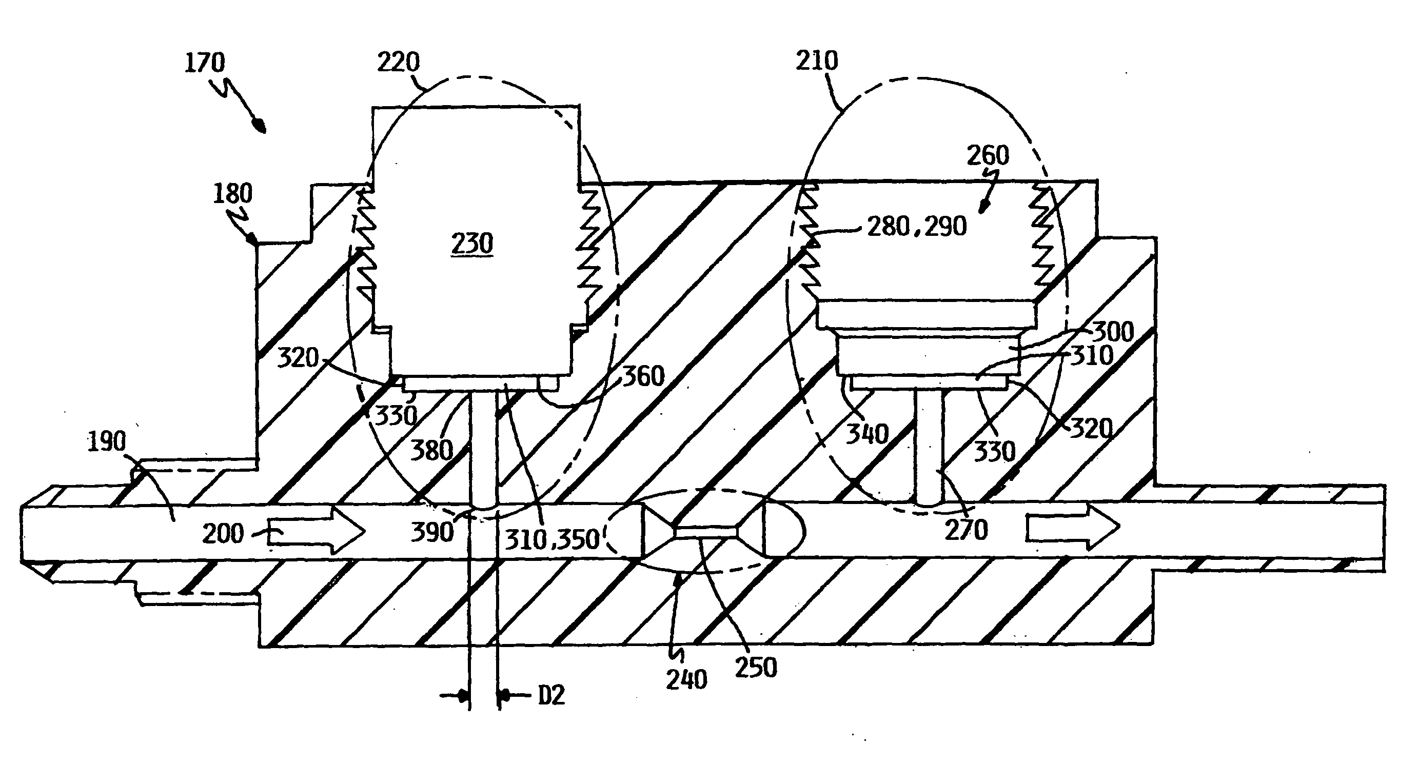
[0027]Referring to FIG. 1, the body 20 of a prior art orifice-type flow meter 10 is shown in cross-section. As discussed in the Background, this design features recesses 30, 40 that are formed with threaded walls 50 to engage a pressure sensor 60 (second pressure sensor not shown). Each recess 30 and 40 is in fluid communication with a flow passage 70 through orifices 90, 100, respectively. The orifices 90 and 100 are characterized by an aspect ratio AR (axial length L to diameter D) on the order of 0.1. Looking at recess 30, a sensing face 110 of the pressure sensor 60 is closely coupled to the flow passage 70 through the orifice 90.
[0028]The aspect ratio of the design in FIG. 1 balances thermal isolation of the sensor with the conflicting design consideration that the depth of any offset between the flow passage 70 and the sensor face 110 should be shallow to reduce areas of stagnant flow that both harbor bacterial growth and particulates and are difficult and time consuming to fl...
PUM
 Abstract
Description
Claims
Application Information