Fluid handling device with isolating chamber

a technology of flue gas and isolating chamber, which is applied in the direction of valve operating means/releasing devices, instruments, pressure difference measurement between multiple valves, etc., can solve the problems of avoid undesirable signal bias and noise, and avoid regions of stagnant fluid , the effect of facilitating bacterial growth

Active Publication Date: 2011-05-17
ENTEGRIS INC
View PDF9 Cites 22 Cited by
  • Summary
  • Abstract
  • Description
  • Claims
  • Application Information

AI Technical Summary

Benefits of technology

[0008]Embodiments of the present invention address the need of the industry for flow metering and controlling devices wherein sapphire or other sensors may be placed in direct contact with a process fluid while avoiding undesirable signal bias and noise from thermal effects, while simultaneously avoiding regions of stagnant fluid harboring particulates and facilitating bacterial growth. According to embodiments of the invention, the face of a sapphire sensor is isolated from the flow stream with an impulse chamber or tube. In one embodiment, fluid communication between the sensor and the flow passage is provided through an impulse chamber having an aspect ratio (that is, the ratio of the length of the chamber to diameter of the chamber), not less than about 3 to 1 and not greater than about 10 to 1.
[0010]It is believed that, in embodiments of the invention, conduction of heat through the process fluid is reduced due to the relatively smaller cross-sectional area dimension and additional length of heat transfer path through the fluid from the heat source to the sensor face. Further, the impulse chamber results in relatively less fluid turbulence and correspondingly less rapid fluid temperature variation at the sensor face. Moreover, conduction of heat through the body of the device is reduced due to the longer heat flow path through the body. These reductions of heat flow through the fluid and device body result in alleviation of signal bias and noise.
[0011]Accordingly, an advantage of embodiments of the invention incorporating an impulse chamber having the above described range of aspect ratios is that it provides improved thermal isolation of the sensor from the turbulent mixing of the flow stream, while allowing adequate flushing of the impulse chamber during initial operation and use.
[0013]An advantage of embodiments of the invention including a sensing chamber with the above characteristics is that it accommodates sensor diameters that may be of larger hydraulic diameter than a practicable impulse chamber, while not enabling excessive particle harboring or bacterial growth.

Problems solved by technology

These reductions of heat flow through the fluid and device body result in alleviation of signal bias and noise.

Method used


Image

  • Fluid handling device with isolating chamber
  • Fluid handling device with isolating chamber
  • Fluid handling device with isolating chamber

Examples


Embodiment Construction

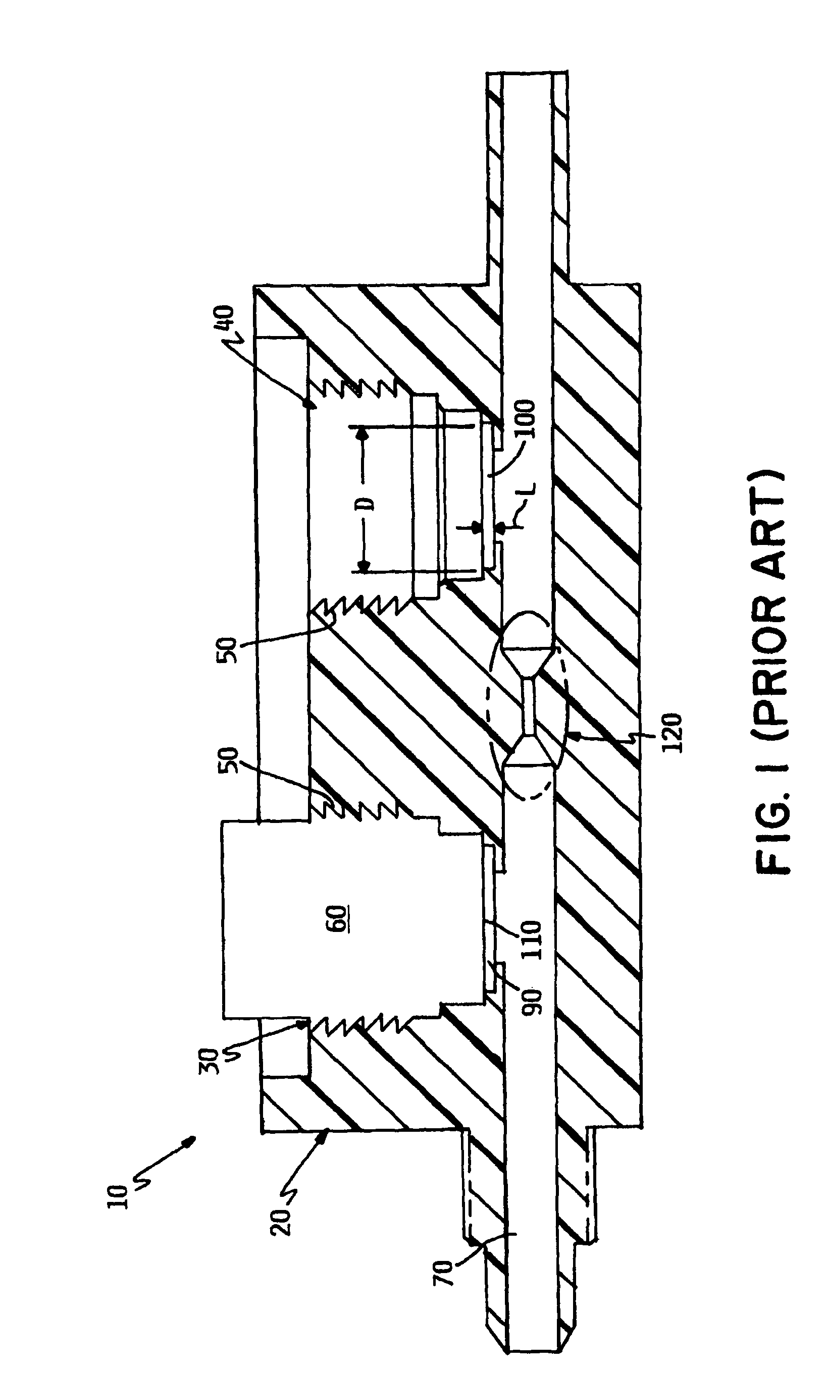
[0027]Referring to FIG. 1, the body 20 of a prior art orifice-type flow meter 10 is shown in cross-section. As discussed in the Background, this design features recesses 30, 40 that are formed with threaded walls 50 to engage a pressure sensor 60 (second pressure sensor not shown). Each recess 30 and 40 is in fluid communication with a flow passage 70 through orifices 90, 100, respectively. The orifices 90 and 100 are characterized by an aspect ratio AR (axial length L to diameter D) on the order of 0.1. Looking at recess 30, a sensing face 110 of the pressure sensor 60 is closely coupled to the flow passage 70 through the orifice 90.

[0028]The aspect ratio of the design in FIG. 1 balances thermal isolation of the sensor with the conflicting design consideration that the depth of any offset between the flow passage 70 and the sensor face 110 should be shallow to reduce areas of stagnant flow that both harbor bacterial growth and particulates and are difficult and time consuming to fl...


PUM

PropertyMeasurementUnit
aspect ratioaaaaaaaaaa

Abstract

A fluid handling device includes a body portion defining a flow passage and an impulse chamber extending from the flow passage. The impulse chamber is fluidly coupled with the flow passage and has a pair of opposing ends defining a length dimension therebetween. The impulse chamber further presents a diameter dimension transverse to the length dimension, wherein the length dimension is at least 3 times and not greater than 10 times the diameter dimension. The device further includes at least one sensor operably coupled with the body portion. The sensor is disposed proximate the end of the impulse chamber opposite the flow passage and presents a sensing face facing into the impulse chamber.

Description

RELATED APPLICATIONS[0001]This application claims the benefit of U.S. Provisional Patent Application No. 60 / 780,537, filed Mar. 9, 2006, and entitled FLOW MEASURING DEVICE BODY, hereby fully incorporated herein by reference.FIELD OF THE INVENTION[0002]This invention relates to fluid flow measurement and control devices. Specifically, it is directed to flow meters and controllers suitable for critical process fluid handling equipment.BACKGROUND OF THE INVENTION[0003]Ultra-pure fluids including de-ionized water are frequently used for processing of sensitive materials such as semi-conductor substrates. The susceptibility to contamination of the sensitive materials during the manufacturing process is a significant problem faced by manufacturers. The sensitive materials under process are often in direct contact with the ultra-pure fluids. Hence, contamination of the ultra-pure fluids often results in contamination of the materials under process. Various components of these manufacturing...

Claims


Application Information

Patent Timeline
Patent Type & Authority Patents(United States)
IPC IPC(8): G01F1/37G01F1/34G01L15/00G01L9/04
CPCG01F1/36
Inventor PETERSON, THOMAS
Owner ENTEGRIS INC
Why Eureka
Try Eureka