
Spark plug for internal combustion engine

a technology for spark plugs and internal combustion engines, which is applied in the manufacture of spark plugs, sparking plugs, electrical equipment, etc., can solve the problems of stress difference between unsatisfactory heat dissipation properties, and deformation or distortion of ground electrodes and noble metal tips, so as to save time-consuming jobs, increase the number of worker hours, and increase the cost

Active Publication Date: 2009-05-21
NGK SPARK PLUG CO LTD
View PDF14 Cites 20 Cited by
  • Summary
  • Abstract
  • Description
  • Claims
  • Application Information

AI Technical Summary

Benefits of technology

[0008]The present invention was made in consideration of the above circumstances, and an object thereof is to provide a spark plug for an internal combustion engine capable of improving ignitability and flame propagation capability and preventing a decrease in peel resistance due to the oxide scale.

Problems solved by technology

Consequently, heat dissipation property (heat conductance from the ground electrode to the metal shell) will become unsatisfactory, and a higher temperature will be easily reached.
Further, due to a dimensional difference in thermal expansion and shrinkage between these two elements, a stress difference occurs in the boundary between the noble metal tip and the ground electrode when viewed from the distal end surface of the ground electrode.
As a result, the ground electrode and noble metal tip are subject to deformation or distortion.

Method used


Image

  • Spark plug for internal combustion engine
  • Spark plug for internal combustion engine
  • Spark plug for internal combustion engine

Examples


Embodiment Construction

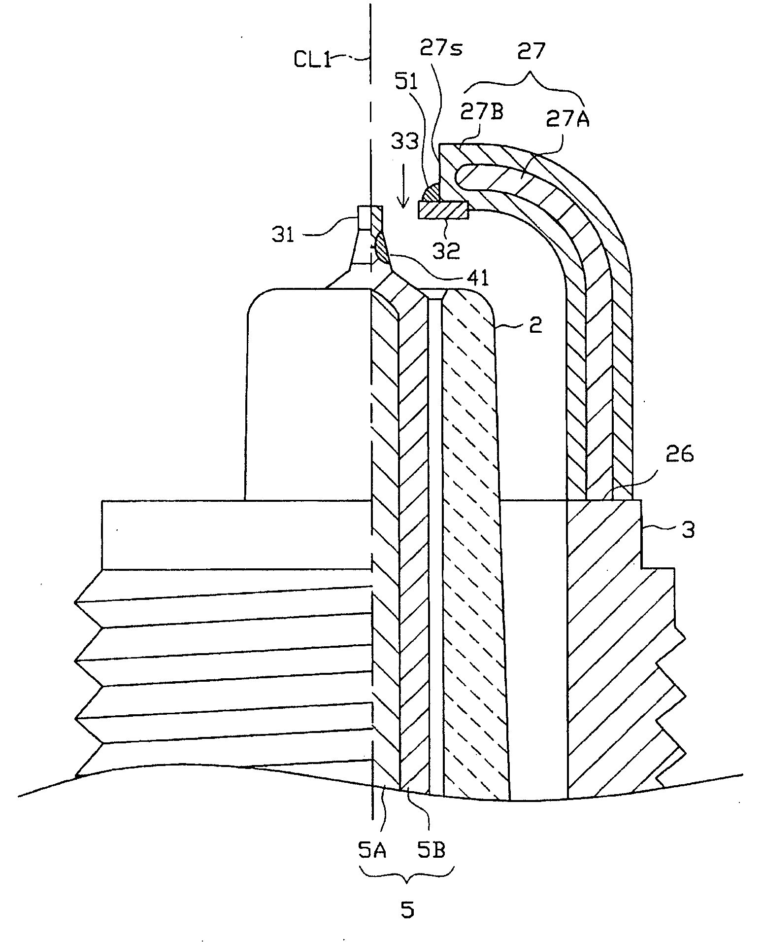
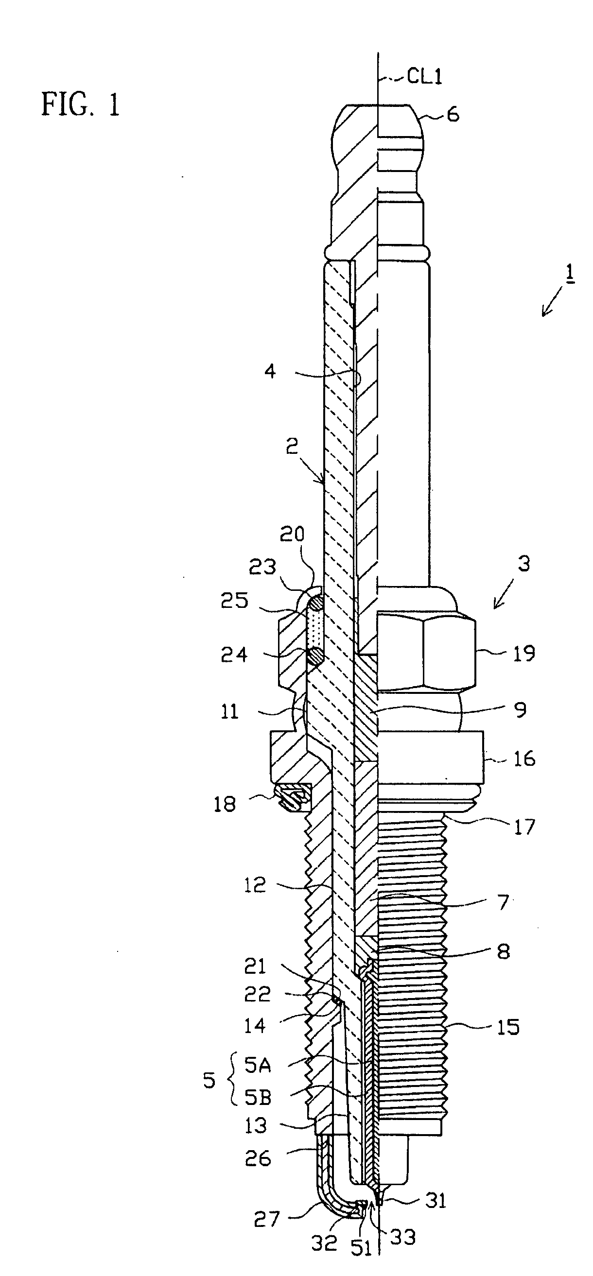
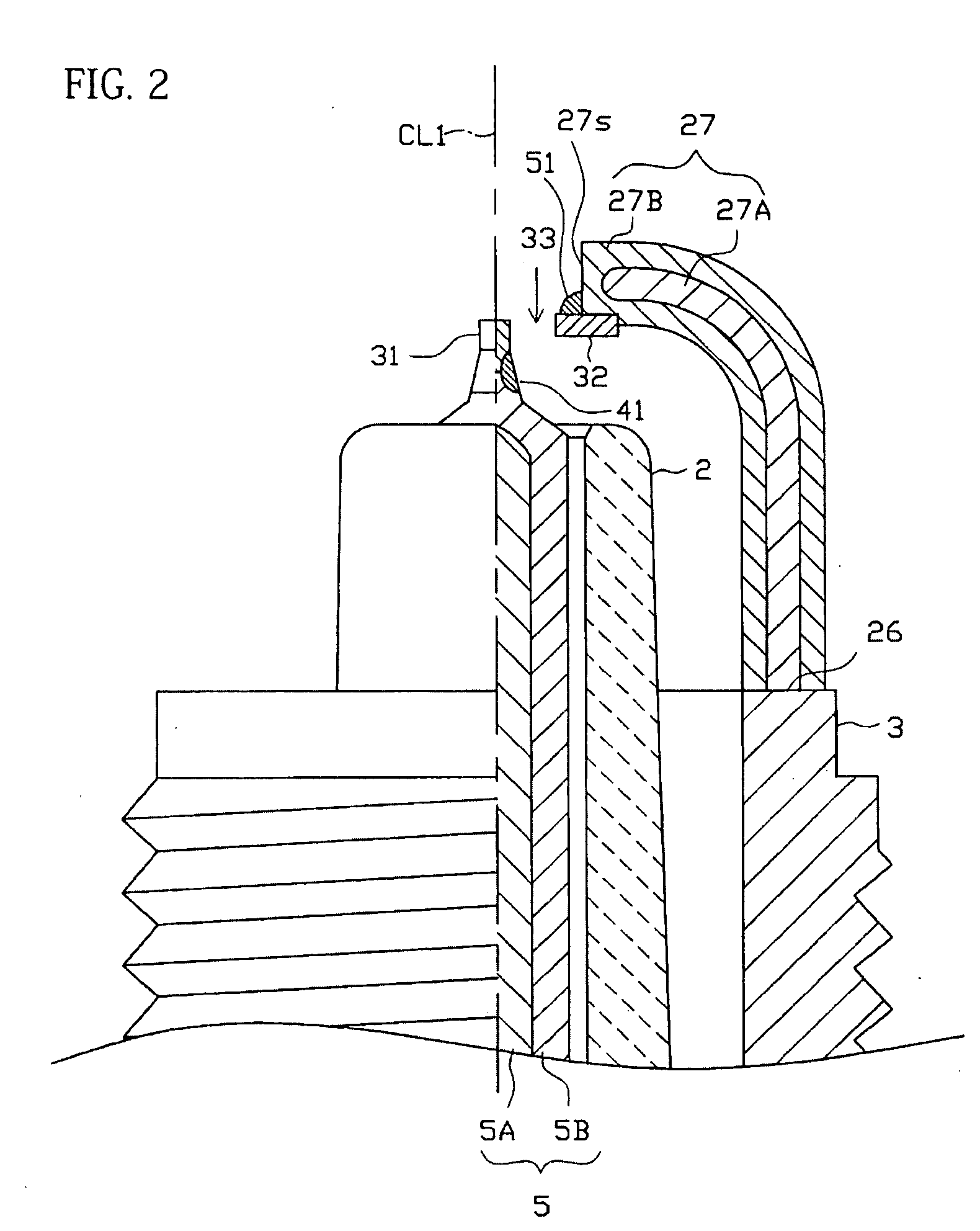
[0059]An embodiment of the present invention is next described with reference to the drawings. However, the present invention should not be construed as being limited thereto. FIG. 1 is a partial sectional view of a spark plug 1. In the description, a direction of an axis line CL1 of the spark plug 1 (also referred to as an axial direction) corresponds to a vertical direction in FIG. 1. In addition a lower side in FIG. 1 corresponds to a leading end side of the spark plug 1, and an upper side in FIG. 1 corresponds to a base end side of the spark plug 1.

[0060]The spark plug 1 includes an insulator 2 serving as an insulating material and a cylindrical metal shell 3 holding the insulator 2.

[0061]The insulator 2 has an axial hole 4 penetrating therethrough along the axis line CL1. A center electrode 5 is inserted and fixed to the leading end portion of the axial hole 4, whereas a terminal electrode 6 is inserted and fixed to the base end portion thereof A resistor 7 is disposed between ...


PUM


Abstract

A spark plug including: a rod-shaped center electrode; an insulator; a metal shell; a ground electrode joined to the metal shell and bent toward the center electrode; a noble metal tip joined to an end portion of the ground electrode and opposing a leading end portion of the center electrode via a gap; and a bulge portion. A part of the noble metal tip is embedded in the ground electrode, and another part of the noble metal tip protrudes from a distal end surface of the ground electrode. A relationship A≧0.25 mm is satisfied where A (mm) is a protruding length of the noble metal tip from the distal end surface. The bulge portion covers a center part of a boundary between the noble metal tip and the end surface in a width direction.

Description

BACKGROUND OF THE INVENTION[0001]1. Field of the Invention[0002]The present invention relates to a spark plug used for an internal combustion engine.[0003]2. Description of the Related Art[0004]A spark plug used for an internal combustion engine, such as an automobile engine, includes a center electrode extending in a direction of an axial line thereof, an insulator disposed radially outside the center electrode, a cylindrical metal shell disposed radially outside the insulator, and a ground electrode having a base end portion joined to a leading end surface of the metal shell. The ground electrode has a substantially rectangular shape in cross section, and the inner surface of the leading end portion thereof is disposed to face the leading end portion of the center electrode. As a result, a spark discharge gap is defined between the leading end portion of the center electrode and the leading end portion of the ground electrode.[0005]In recent years, tips (noble metal tips) containi...

Claims


Application Information

Patent Timeline
IPC IPC(8): H01T13/26H01T21/02
CPCH01T13/32H01T21/02H01T13/39H01T13/20
Inventor KAMEDA, HIROYUKIMUSASA, MAMORU
Owner NGK SPARK PLUG CO LTD
Learn More