Calibration techniques for imaging devices

a color imaging and calibration technology, applied in the field of color imaging, can solve the problems that the accuracy of the calibration process can substantially affect the color accuracy, and achieve the effect of improving color accuracy

Inactive Publication Date: 2009-05-21
EDGE CHRISTOPHER J
View PDF1 Cites 16 Cited by
  • Summary
  • Abstract
  • Description
  • Claims
  • Application Information

AI Technical Summary

Benefits of technology

[0007]In general, the invention is directed to various calibration techniques for calibrating an imaging device such as a display device, a printer or a scanner. The techniques may involve characterizing the imaging device with a device model, wherein an average error between an expected value of the device model and measured output of the image device is on the order of an expected error. The invention can achieve a balance between analytical behavior of the imaging device and measured output. In this manner, adjustments to image data may be more likely to improve color accuracy and less likely to overcompensate for errors that are expected.
[0014]The invention is capable of providing a number of advantages. In particular, the invention can improve calibration of imaging devices. Moreover, improved calibration can facilitate the realization of color intensive applications such as soft proofing. In some cases, the invention can be used to calibrate imaging devices such that measured errors of the imaging device are on the order of expected errors. For example, expected errors in the measurements may be caused by factors unrelated to the imaging device, such as errors introduced by the measuring device or the video card. The invention can achieve a balance between theory and measurement to ensure that adjustments to image data do not overcompensate for measured errors unrelated to the imaging device itself. In this manner, an imaging device can be calibrated such that an average color error is approximately less than (0.75 delta e) from an analytical expected color output.

Problems solved by technology

The effectiveness and accuracy of the calibration process can substantially impact color accuracy.

Method used


Image

  • Calibration techniques for imaging devices
  • Calibration techniques for imaging devices
  • Calibration techniques for imaging devices

Examples


Embodiment Construction

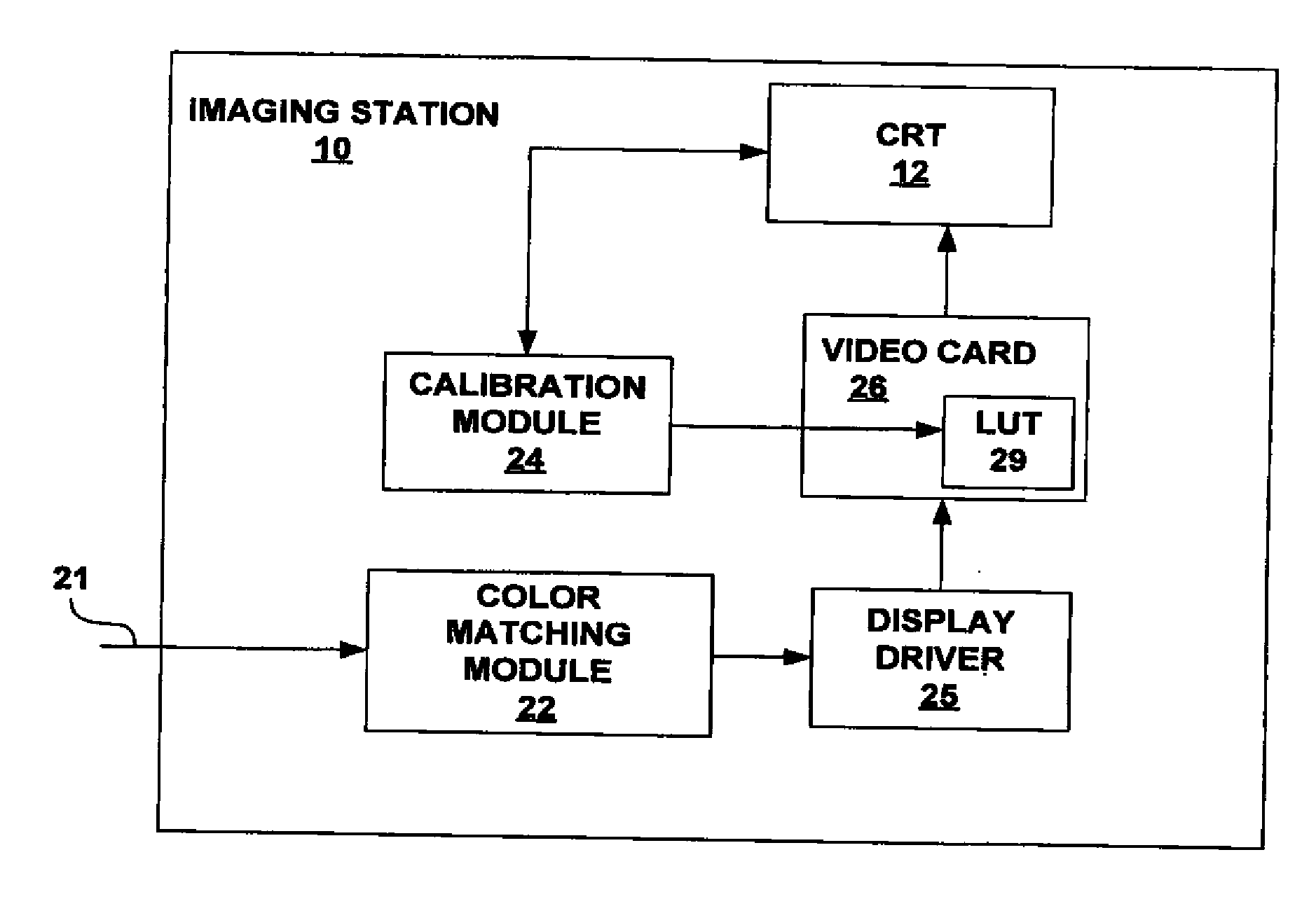
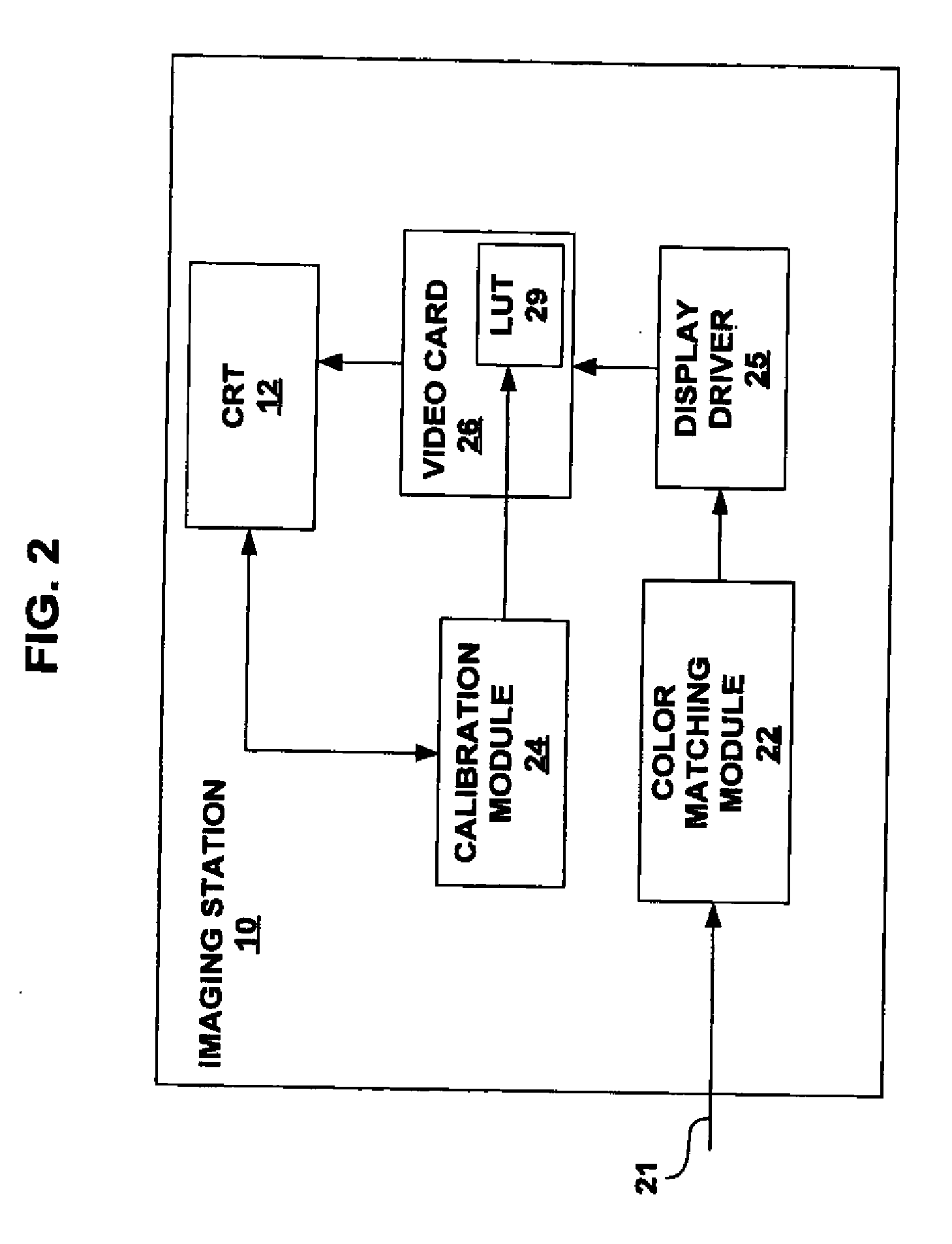
[0023]In the discussion that follows, many aspects of the invention are described with reference to the calibration of an imaging device in the form of a cathode ray tube (CRT). However the invention is not necessarily limited in that respect. For example, techniques according to the principles of the invention may be readily applicable to other imaging devices, including other display devices such as liquid crystal displays, plasma displays, projection displays, and the like; printing devices such as printing presses, laser printers, ink-jet printers, dot-matrix printers, or any other printing device; and other imaging devices such as scanners. Accordingly, the detailed discussion is meant to be an exemplary description of one detailed embodiment in accordance with the invention.

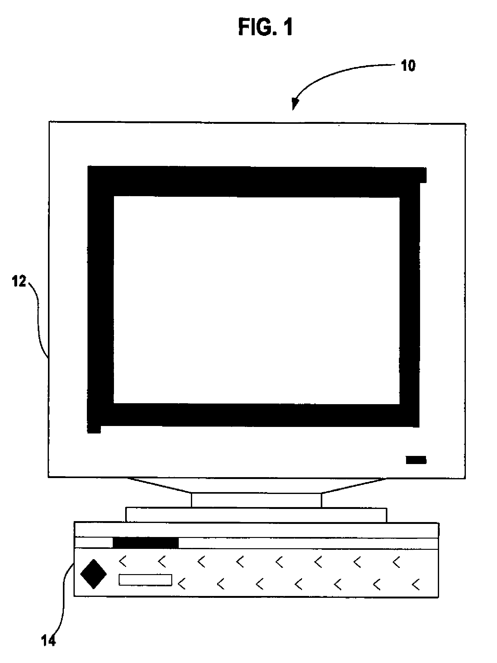
[0024]FIG. 1 is a front view of an exemplary imaging station 10. Imaging station 10 includes an imaging device in the form of a cathode ray tube (CRT) 12. In addition, imaging station 10 includes a computer...


PUM


Abstract

The invention is directed to various calibration techniques for calibrating an imagining device such as a display device, a printer, or a scanner. The techniques may involve characterizing the imaging device with a device model such that an average error between expected outputs determined from the device model and measured outputs of the imaging device is on the order of an expected error, and adjusting image rendering on the imaging device to achieve a target behavior. The invention can achieve a balance between analytical behavior of the imaging device and measured output. In this manner, adjustments to image rendering may be more likely to improve color accuracy and less likely to overcompensate for errors that are expected.

Description

CROSS REFERENCE TO RELATED APPLICATIONS[0001]This is a Continuation of prior U.S. patent application Ser. No. 10 / 854,113, filed May 26, 2004, which is a Divisional of U.S. patent application Ser. No. 10 / 039,669, filed Dec. 31, 2001, now issued as U.S. Pat. No. 6,775,633, issued Aug. 10, 2004, all of which documents cited in this section are hereby incorporated in their entirety herein by reference.FIELD OF THE INVENTION[0002]The invention relates to color imaging and, more particularly, to calibration techniques for color imaging devices.BACKGROUND OF THE INVENTION[0003]Calibration of an imaging device can significantly improve color accuracy of images rendered by the device. For example, imaging devices such as cathode ray tubes, liquid crystal displays, plasma displays, and various printing devices, are often calibrated to determine adjustments that can be applied to either color input or drive data applied to the device. In either case, the adjusted data can then be used to contr...

Claims


Application Information

Patent Timeline
Patent Type & Authority Applications(United States)
IPC IPC(8): H04N1/46B41J5/30G06T1/00G09G5/00G09G5/02H04N1/60H04N9/69H04N17/02H04N17/04
CPCH04N1/6033H04N17/04H04N17/02
Inventor EDGE, CHRISTOPHER J.
Owner EDGE CHRISTOPHER J
Why Eureka
Try Eureka