Image forming apparatus including image transporting belt and rotary roll

a technology rotary roll, which is applied in the direction of electrographic process apparatus, thin material handling, instruments, etc., can solve the problems of low image quality, high cost, and complex structure, and achieve good color multilayer accuracy and stable running performance of image transporting bel

Inactive Publication Date: 2005-02-08
FUJIFILM BUSINESS INNOVATION CORP
View PDF2 Cites 8 Cited by
  • Summary
  • Abstract
  • Description
  • Claims
  • Application Information

AI Technical Summary

Benefits of technology

The invention has been made in order to solve the above technical problems, and its object is to provide an image forming apparatus in which a load applied onto an image transporting belt due to the peripheral speed difference is reduced, stable running performance of the image transporting belt is secured and accuracy of color multilayer is good.

Problems solved by technology

However, in case that the velocity of the intermediate transfer belt varies, position errors of the layered toner images of the respective color components are produced, so that a color registration error occurs on the sheet, which causes a technical problem that quality of image lowers.
Due to pressure-contact of a second transfer roll with the intermediate transfer belt in the above image forming cycle, and passing of the sheet between the intermediate transfer belt and the second transfer roll, such the technical problem is caused.
Further, in this method, since the torque limiter is necessary for drive torque transmission of the second transfer roll, the structure becomes complicated, and cost becomes high.

Method used


Image

  • Image forming apparatus including image transporting belt and rotary roll
  • Image forming apparatus including image transporting belt and rotary roll
  • Image forming apparatus including image transporting belt and rotary roll

Examples


first embodiment

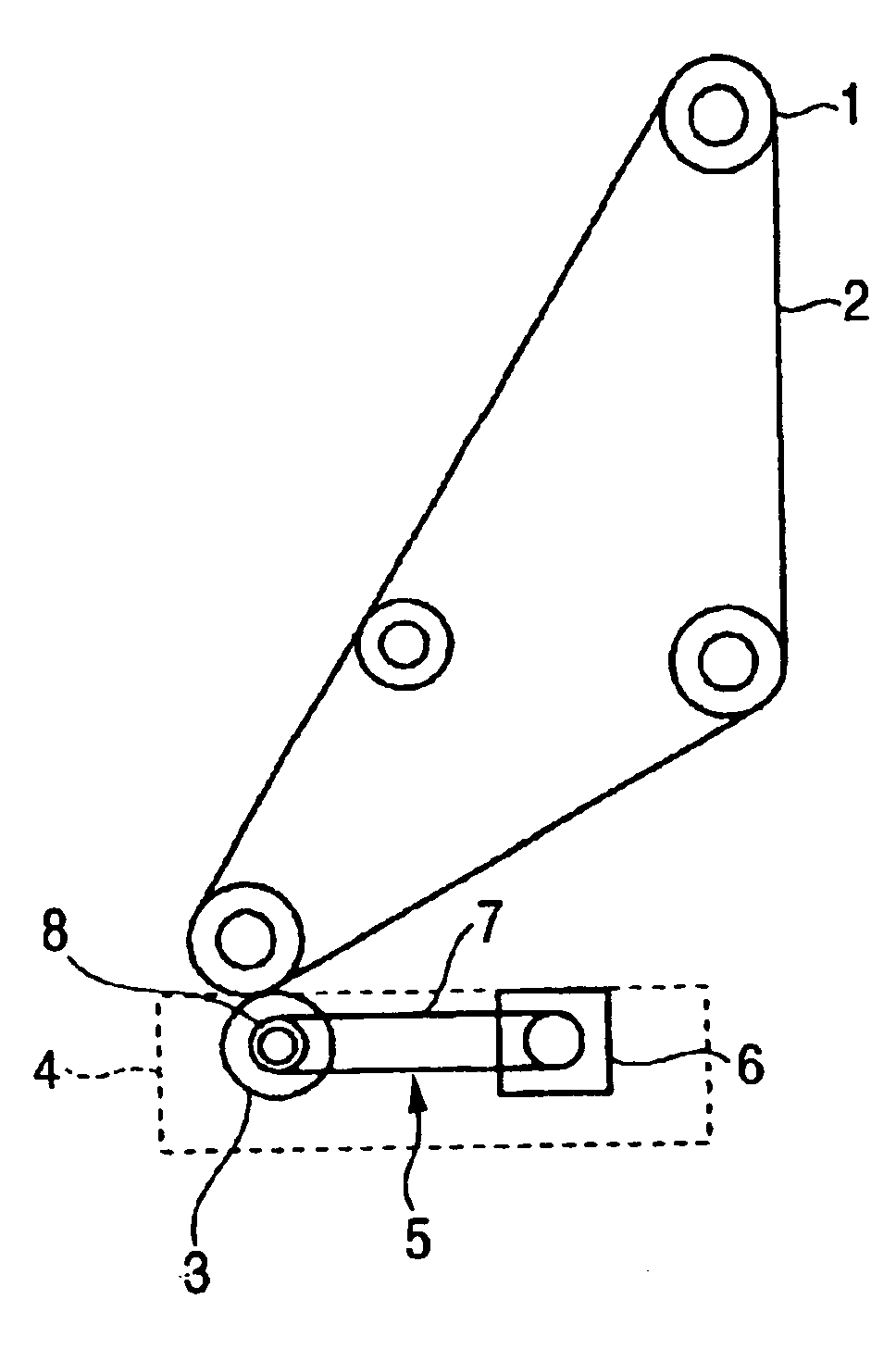
FIG. 3 shows a first embodiment of an image forming apparatus to which the invention is applied.

FIG 3, the image forming apparatus includes, in an apparatus body 50, a photoconductor drum 20, and an intermediate transfer belt 30 arranged opposed to the photoconductor drum 20 in order to transfer a toner image from this photoconductor drum 20 thereon, and it is a four-cycle intermediate transfer type image forming apparatus in which multilayer transfer of four times is performed on the intermediate transfer belt 30 in order to obtain a color image of four colors.

In the embodiment, the photoconductor drum 20 has a photoconductive layer of which a resistance value lowers by irradiation of light. Around this photoconductive drum 20, there are arranged a charging device 21 that charges the photoconductor drum 20, an exposure device 22 that forms a electrostatic latent image of each color component (in this example, black (K), yellow (Y), magenta (M), and cyan (C)) on the charged photocon...

second embodiment

FIG. 5 shows a second embodiment of the image forming apparatus to which the invention is applied, in which a drive 70 device is shown.

In FIG. 5, a drive device 70 according to this embodiment has an elastic drive power transmitting belt 62 similar to the drive device 60 in the first embodiment. However, the drive device 70 in this embodiment is different from the first embodiment in that an intermediate transfer belt 30 and a second transfer roll 35 are driven by drive power from the same drive source 71.

The drive device 70 according to this embodiment is, as shown in FIG. 5, provided with the drive source 71, and a timing belt 72 laid between an end portion of a drive shaft 71a of this drive source 71 and a pulley 73 provided for an end portion (on the left in this embodiment) of a rotary support shaft 31a of a tension roll 31 (drive roll 31), while an elastic drive power transmitting belt 62 is laid between an end portion of the drive shaft 71a closer to the drive source 71 side ...

third embodiment

FIG. 6 shows a third embodiment of the image forming apparatus to which the invention is applied, in which a drive device 80 is shown.

In FIG. 6, a drive device 80 according to this embodiment has an elastic drive power transmitting belt 62 similar to the drive device 70 in the second embodiment. However, the drive device 80 in this embodiment is different from the second embodiment in that a second transfer roll 35 is rotationally driven by a drive roll 31 of an intermediate transfer belt 30.

In this embodiment, in the drive device 80, as shown in FIG. 6, an elastic drive power transmitting belt 62 is laid between a pulley 73 provided for an end portion (on the right in this embodiment) of a rotary support shaft 35a of the second transfer roll 35 and a tension roll 31 (drive roll 31) of the intermediate transfer belt 30, and a drive source 71 is provided for an end (on the left in this example) of a rotary support shaft 31a of the drive roll 31.

Further, outer diameter of the pulley 7...


PUM


Abstract

In an image forming apparatus provided with an image transporting belt that holds an image directly or indirectly and is laid on a plurality of tension rolls thereby to move circularly, and a sub-unit having a rotary roll that comes into contact with this image transporting belt and is rotationally driven by a drive section, the drive section includes a drive source, and an elastic drive power transmitting member that transmits drive power from the drive source and absorbs difference in peripheral speed produced between the image transporting belt and the rotary roll. The drive section includes a slip transmission member that engages with the elastic drive power transmitting member and slips under a condition over a peripheral speed difference absorbable range of the elastic drive power transmitting member.

Description

The present disclosure relates to the subject matter contained in Japanese Patent Application No. 2002-073975 filed Mar. 18, 2002 and Japanese Patent Application No. 2002-186599 filed Jun. 26, 2002, which are incorporated herein by reference in their entirety.BACKGROUND OF THE INVENTION1. Field of the InventionThe present invention relates to an image forming apparatus such as a copying machine and a printer, and particularly to an image forming apparatus which uses an image transporting belt that holds an image directly or indirectly and moves circularly.2. Description of the Related ArtConventionally, as this type of image forming apparatus, there is an intermediate transfer type of image forming apparatus that adopts an electrophotographic system. In this image forming apparatus, a toner image of each color component (for example, Y (yellow), M (magenta), C (cyan), and K (black)) is formed on an image holding member such as a photoconductor drum, and these toner images are tempor...

Claims


Application Information

Patent Timeline
Patent Type & Authority Patents(United States)
IPC IPC(8): G03G15/00G03G15/01G03G15/16G03G21/00B65H5/06
CPCG03G15/0131G03G15/1615G03G15/5008G03G15/161
Inventor SUZUKI, WATARUKITAMURA, ATSUYUKIKURAMOTO, SHINICHISATO, MASAHIROYAMAMOTO, MITSUOWATANABE, KOICHINISHIDE, SHUICHI
Owner FUJIFILM BUSINESS INNOVATION CORP
Why Eureka
Try Eureka