Optical element driving device and imaging apparatus

a driving device and optical element technology, applied in the field of optical element driving devices and imaging apparatus, can solve the problems of increasing the size of the lens driving device, difficult to reduce the thickness of the camera main body, and inaccurate driving of the lens, so as to reduce the size of the optical element driving device and accurately drive the optical elemen

Inactive Publication Date: 2009-05-21
PANASONIC CORP
View PDF2 Cites 27 Cited by
  • Summary
  • Abstract
  • Description
  • Claims
  • Application Information

AI Technical Summary

Benefits of technology

[0014]It is an object to reduce the size of an optical element driving device in the thickne

Problems solved by technology

However, since drive force is imparted to one side of the lens that is driven, the drive center of the drive mechanisms ends up being separated from the movable center of gravity of the portion that moves.
Consequently, the lens driving devices discussed in Patent Documents 1 and 2 tend not to drive t

Method used


Image

  • Optical element driving device and imaging apparatus
  • Optical element driving device and imaging apparatus
  • Optical element driving device and imaging apparatus

Examples


Embodiment Construction

[0047]Selected embodiments of the present invention will now be explained with reference to the drawings. It will be apparent to those skilled in the art from this disclosure that the following descriptions of the embodiments of the present invention are provided for illustration only and not for the purpose of limiting the invention as defined by the appended claims and their equivalents.

[0048]1: Overview of Digital Camera

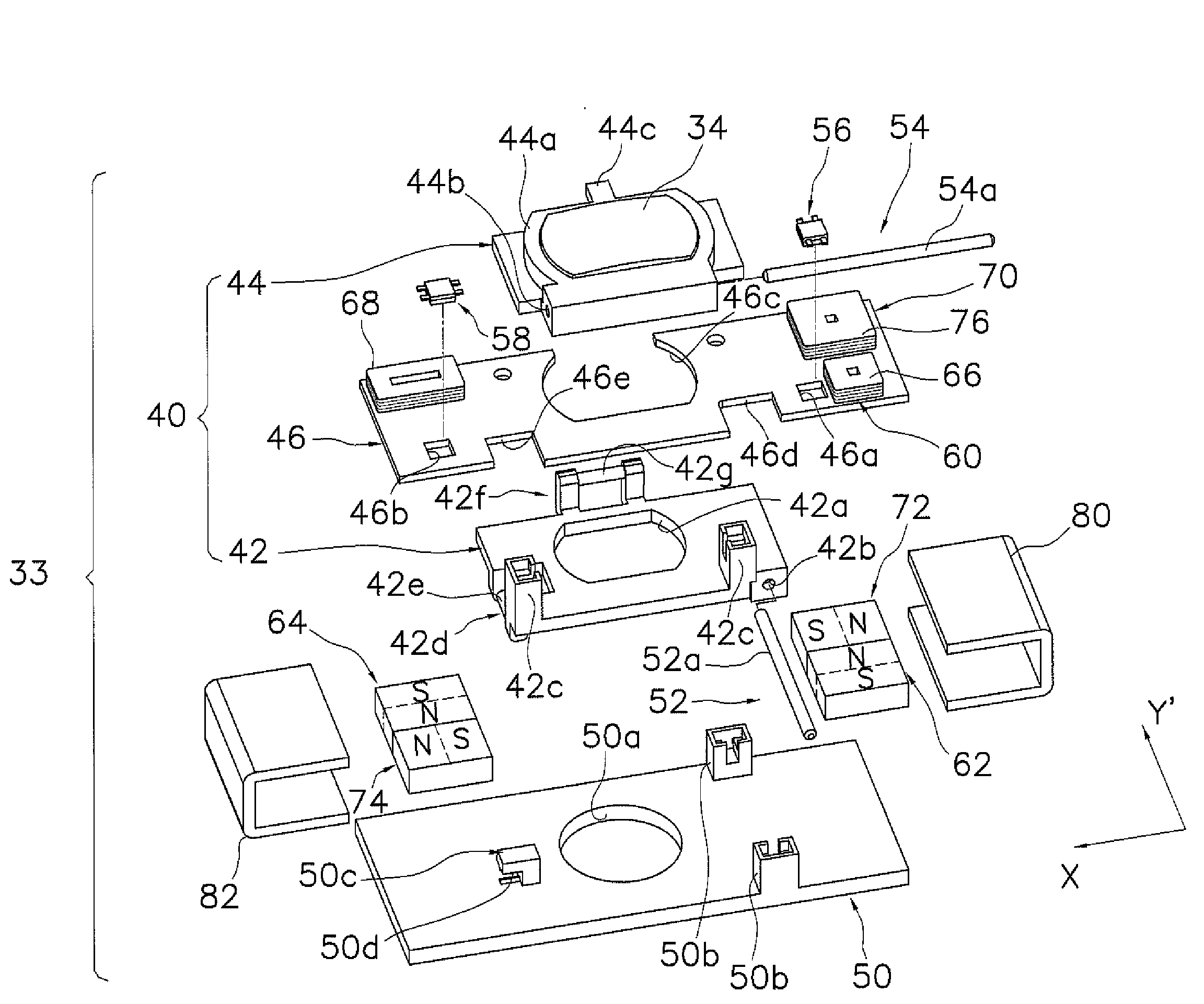
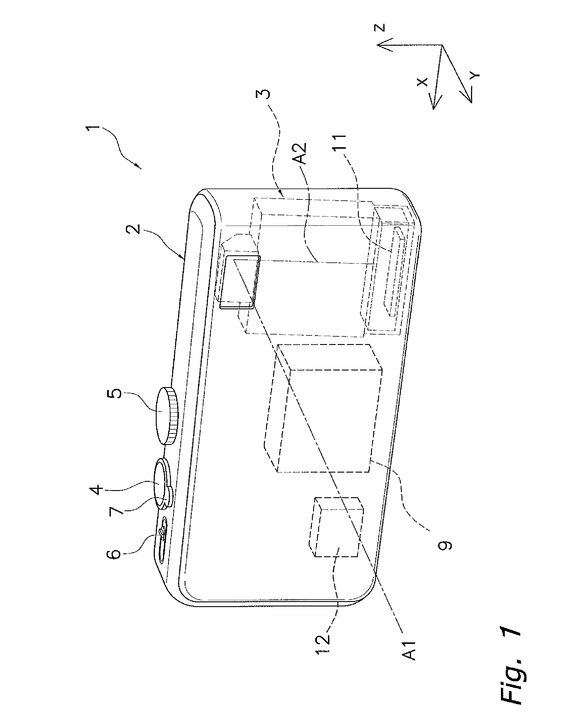
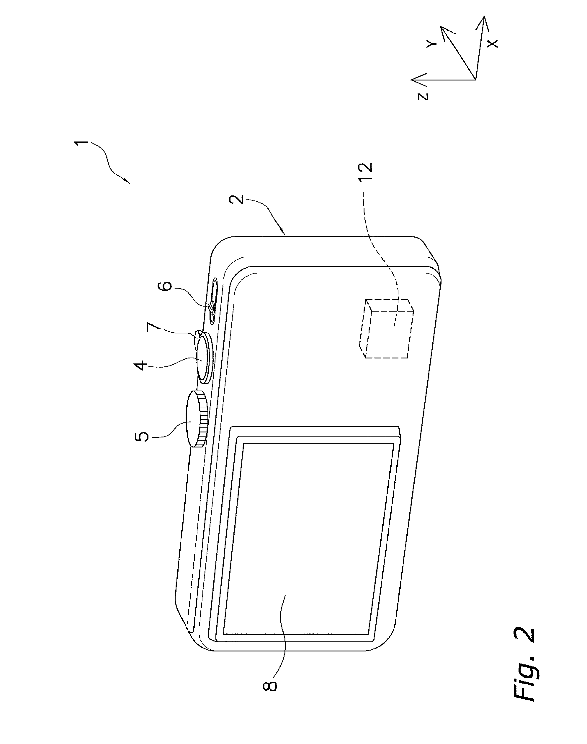
[0049]A digital camera 1 as an example of the imaging apparatus according to an embodiment of the present invention will now be described through reference to FIGS. 1 and 2. FIGS. 1 and 2 are simplified oblique views of the digital camera 1.

[0050]The digital camera 1 is a camera for capturing an image of a subject, and has a substantially rectangular camera main body 2. A lens barrel 3 having an imaging optical system for bending is installed inside the camera main body 2 for increasing magnification and reducing the size of the camera.

[0051]In the following descr...


PUM


Abstract

A lens driving device includes a lens, a moving member that supports the lens, a stationary member that movably supports the moving member, a pitch drive mechanism that drives the moving member in the pitch correction direction, and a yaw drive mechanism that drives in the yaw correction direction. The pitch drive mechanism has first and second magnets provided to the stationary member, and first and second coils provided to the moving member. The yaw drive mechanism has a third magnet provided to the stationary member, and a third coil provided to the moving member. The first and second coils are arranged on opposite sides of the lens when viewed in a third direction that is perpendicular to the pitch and yaw correction directions, and the third coil is arranged on the same side as the first coil with respect to the lens when viewed in the third direction.

Description

CROSS-REFERENCE TO RELATED APPLICATIONS[0001]This application claims priority to Japanese Patent Application No. JP 2007-298546 filed on Nov. 16, 2007. The entire disclosure of Japanese Patent Application No. JP 2007-298546 is hereby incorporated herein by reference.BACKGROUND[0002]1. Technical Field[0003]The technical field relates to an optical element driving device for driving an optical element of an imaging apparatus, and to an imaging apparatus in which this device is used.[0004]2. Description of the Related Art[0005]Recent years have witnessed the practical application of products such as digital imaging apparatus, typified by digital still cameras and digital video cameras, which are equipped with image blur correction mechanisms that correct image blur caused by hand shake in the pitch and yaw directions of the apparatus during image capture. With most image blur correction mechanisms, image blur is corrected by using a lens driving device (an example of an optical element...

Claims


Application Information

Patent Timeline
IPC IPC(8): G02B7/02H02K33/00G03B5/00H02K33/18H04N5/225H04N5/232H04N5/335H04N5/351H04N101/00
CPCG02B7/023H02K2201/18H02K41/0356G02B7/102
Inventor ITO, DAISUKE
Owner PANASONIC CORP
Why Eureka
Try Eureka