
Common key generation system, common key generation method and node using the same

a key generation and key technology, applied in the information technology support system, digital transmission, encryption apparatus with shift register/memory, etc., can solve the problem of individual pieces of information detected at each of the nodes being different, and achieve the effect of stably generating

Inactive Publication Date: 2009-05-21
OKI ELECTRIC IND CO LTD
View PDF20 Cites 12 Cited by
  • Summary
  • Abstract
  • Description
  • Claims
  • Application Information

AI Technical Summary

Benefits of technology

[0011]This permits measurement error due to physical change in each of the two nodes, thus enabling the nodes to stably generate and share the common key.

Problems solved by technology

However, the method disclosed in Japanese Patent No. 3707660 can possibly produce a situation where, even if a user can operate the pushbuttons properly at predetermined times at each of the nodes, individual pieces of information detected at each of the nodes may be different because an error occurs in sensors of the nodes that detect this operation during a sampling process.

Method used


Image

  • Common key generation system, common key generation method and node using the same
  • Common key generation system, common key generation method and node using the same
  • Common key generation system, common key generation method and node using the same

Examples


first embodiment

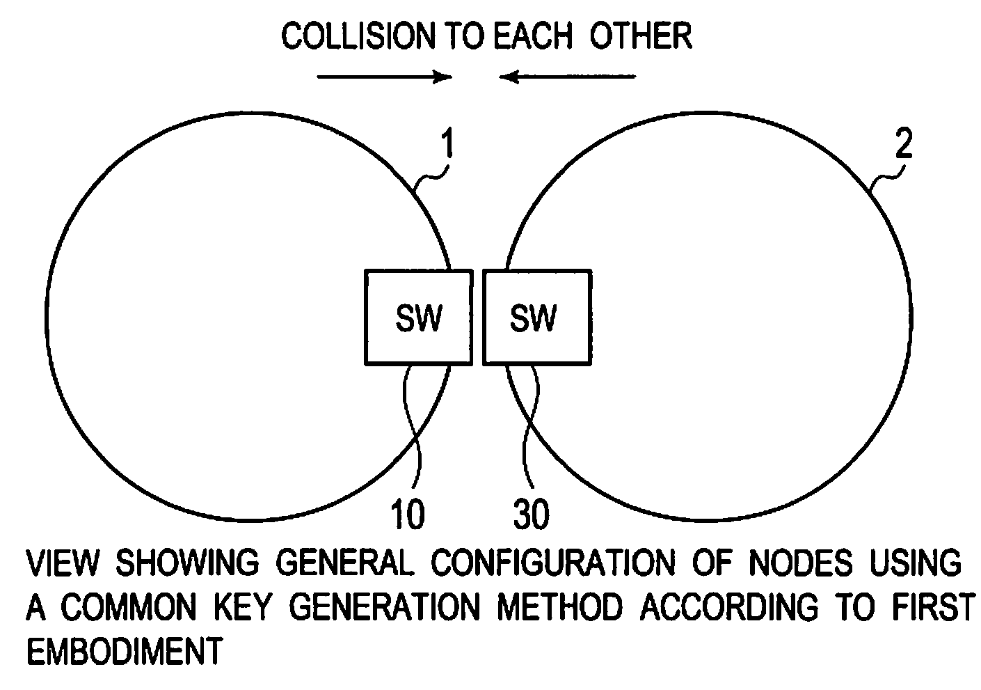
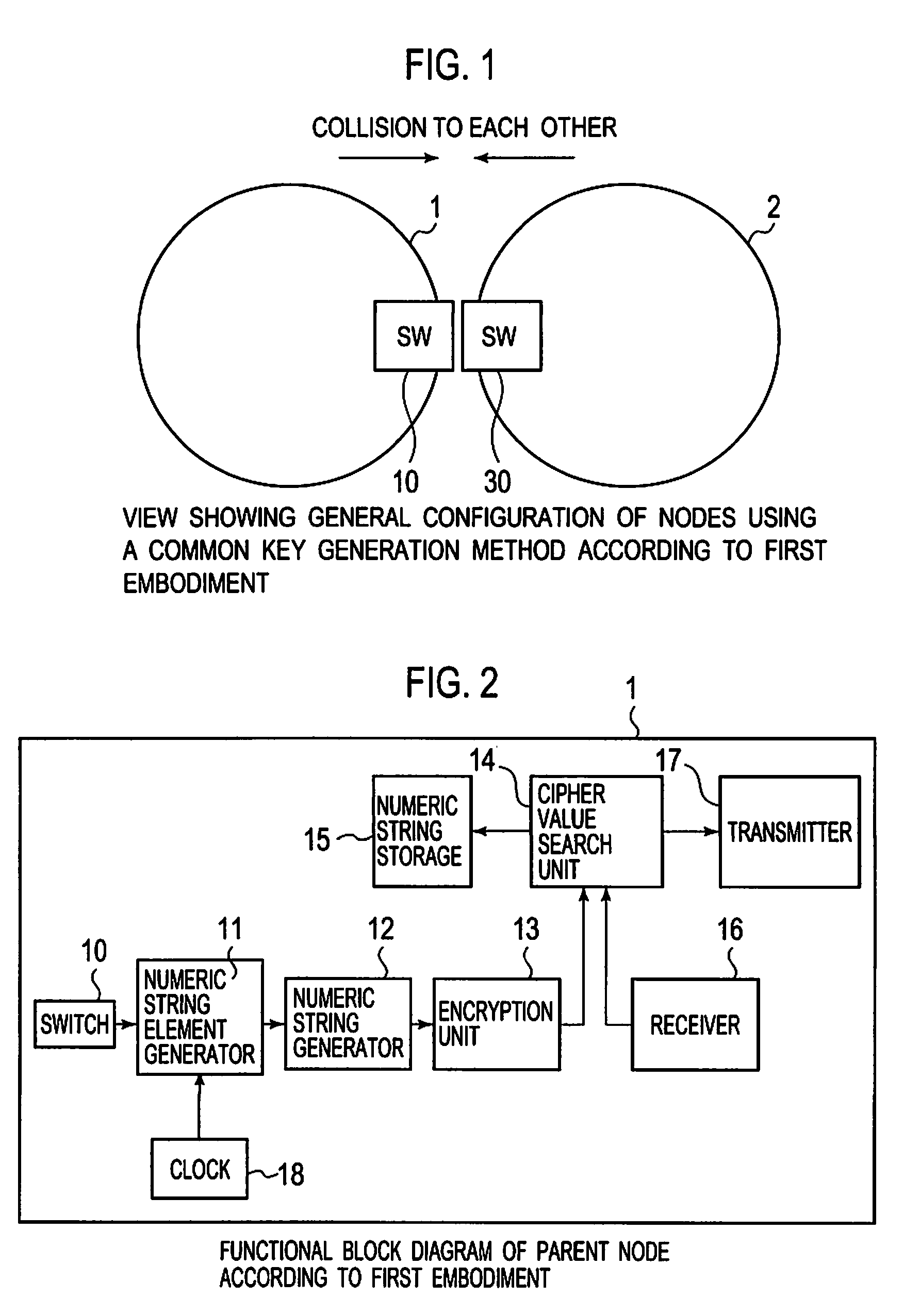
[0031]FIG. 1 is a view showing the general configuration of a node using a common key (i.e. secret key) generation method according to a first embodiment. Nodes 1 and 2 include switches (SW) 10 and 30 exposed to the outside, respectively. By plural collisions of switches 10 and 30 of nodes 1 and 2, nodes 1 and 2 generate shared information based on the time interval between switch-on operations. A process, which will be described later, based on the shared information, is performed to generate a common key. According to the first embodiment, switches 10 and 30 exposed to the outside are used. However, collision detectors may be installed within housings of the nodes to detect the time interval between collisions of the housings.

[0032]Here, the first embodiment is characterized as follows. In some cases, individual portions of sensor information detected by the nodes differ, even in an environment in which the same physical change is detected (e.g., in an environment in which the on-...

second embodiment

[0083]Although the first embodiment uses the time interval value (or the length of time) as original data for basic numeric string generation, the second embodiment uses a time ratio as the original data and further adopts a numeric string element generation rule and a numeric string element substitution rule that are distinct from those for the first embodiment.

[0084]The configurations of parent node 1 and child node 2 according to the second embodiment are the similar to those for the first embodiment. Also, as compared with that shown in FIG. 4, the process flow is different in steps s3 (s23) and s5 (s25) but is the similar in others. Further, the collisions between parent node 1 and child node 2 of the second embodiment are the same as those in the case of the first embodiment.

[0085]Description will be given below with regard to steps s3 (s23) and s5 (s25), which are the process steps that differ from those in the second embodiment from the first embodiment. At step s3, as in th...


PUM


Abstract

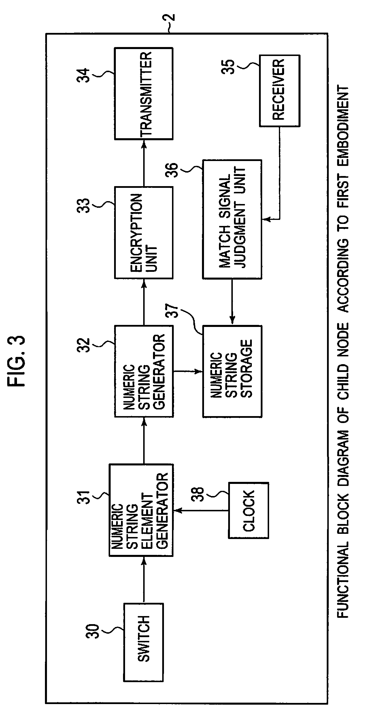
First and second nodes generate numeric string elements from time interval by their physical changes. The first node generates a basic numeric string from the numeric string elements and similar numeric strings, encrypts the generated basic numeric string and the similar numeric strings, and generates a cipher value list that stores the numeric strings with corresponding cipher values. The second node generates a basic numeric string based on the numeric string elements generated by the second node, encrypts the generated basic numeric string in accordance with the same encryption rule as that for the first node, and transmits the generated cipher value to the first node. The first node receives a cipher value from the second node, and compares the received cipher value with the cipher values in the cipher value list to find a match, and transmits a match signal if a match is found.

Description

CROSS REFERENCE TO RELATED APPLICATIONS[0001]This application claims priority based on 35 USC 119 from prior Japanese Patent Application No. P2007-300385 filed on Nov. 20, 2007, entitled “COMMON KEY GENERATION SYSTEM, COMMON KEY GENERATION METHOD AND NODE USING THE SAME” the entire contents of which are incorporated herein by reference.BACKGROUND OF THE INVENTION[0002]1. Field of the Invention[0003]The present invention relates to technology for generating and sharing a common key that is common to nodes (or separate pieces of equipment) having a radio communication function to carry out radio communication based on common key cryptography, without a third party intercepting the communication.[0004]2. Description of the Related Art[0005]Heretofore, as a method for generating a common key, a method involves: making the same physical change in two nodes that desire cipher communication; producing shared information common to the nodes based on the physical change; and generating a com...

Claims


Application Information

Patent Timeline
IPC IPC(8): H04L9/06
CPCH04L2209/805H04L9/0838Y04S40/20
Inventor KONUMA, RYOUHEI
Owner OKI ELECTRIC IND CO LTD
Learn More