
Method for transition between distributed transmission and localized transmission

Active Publication Date: 2009-05-21
SAMSUNG ELECTRONICS CO LTD +1
View PDF4 Cites 53 Cited by
  • Summary
  • Abstract
  • Description
  • Claims
  • Application Information

AI Technical Summary

Benefits of technology

[0027]The BS of the present invention can choose more appropriate transmission modes for downlink transmission based on changing characteristics of the channel in time domain and frequency domain. When choosing transmission mode, it also considers changing characteristics of frequency domain, whereas the traditional method is to choose transmission mode only according to changing characteristics of time domain, the new method allows downlink transmission to use distributed transmission under the channel condition similar to flat fading, thus reducing uplink signalling overhead without reducing transmission gain.

Problems solved by technology

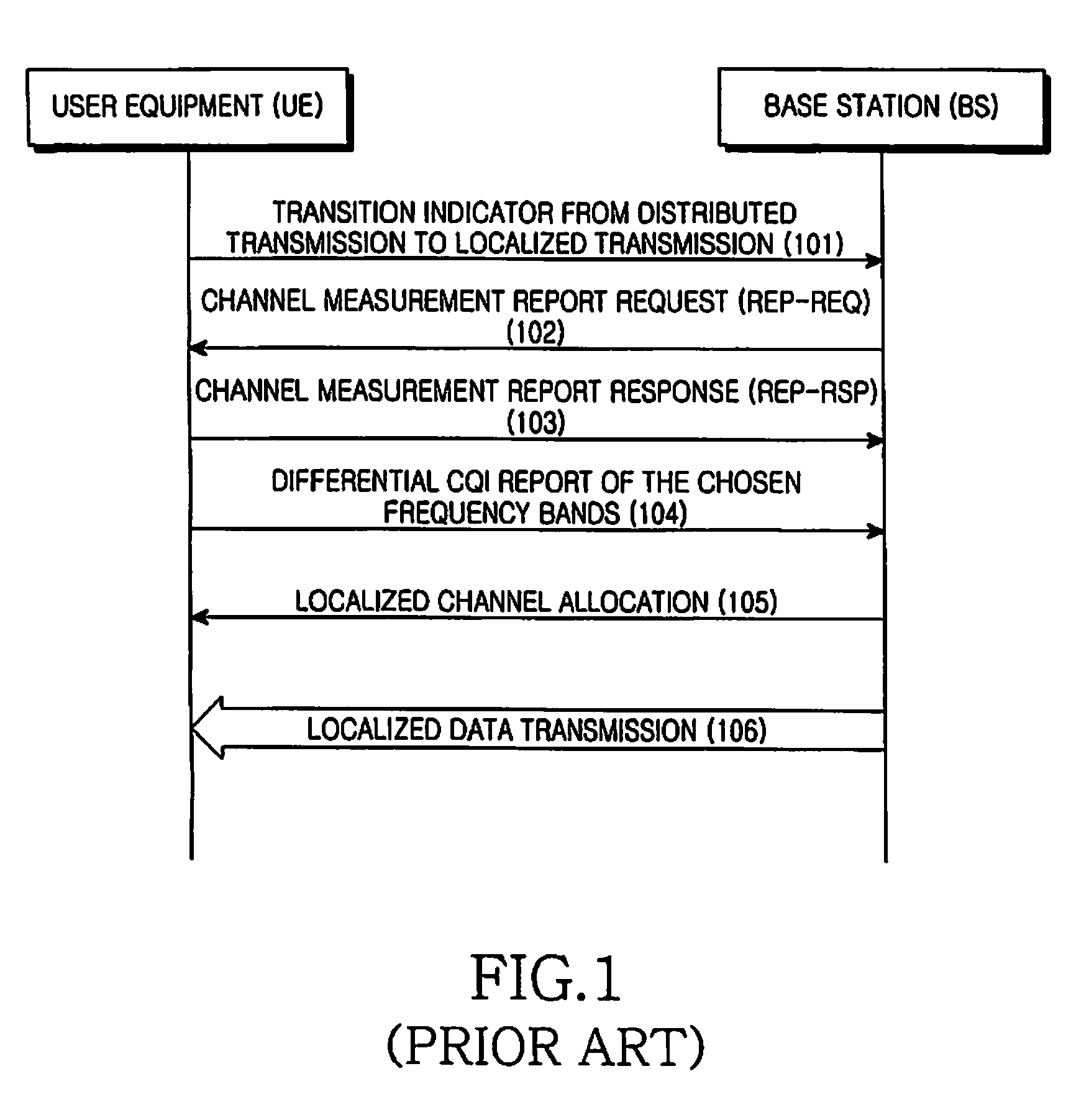
Usually localized data transmission mode which can use adaptive modulation coding and frequency scheduling has greater transmission gain, but to some channels of fast changing speed, channel condition predicted at some time can't reflect that of the next time, therefore localized transmission is hard to implement.
However data transmission in flat fading channel condition, localized data transmission can't acquire much selective frequency gain compared to distributed data transmission, because SNRs of all sub-carriers are basically the same no matter they are localized data transmission carriers or distributed data transmission carriers, thus their adaptive modulation coding gains are basically the same no matter they use distributed transmission or localized transmission.
But localized transmission needs CQI report of uplink multi-bands, thus introducing heavier signalling load compared to distributed transmission.
Therefore the mode transition in IEEE802.16E is not suitable for data transmission mode transition in 3GPP LTE.

Method used


Image

  • Method for transition between distributed transmission and localized transmission
  • Method for transition between distributed transmission and localized transmission
  • Method for transition between distributed transmission and localized transmission

Examples


implementation example

[0059]To clearly illustrate the method proposed in the present invention, an implementation example is given in the following.

[0060]Transition example from distributed transmission to localized transmission is given first:

[0061]Suppose the UE's current downlink data transmission is distributed transmission, and the UE is a low speed moved UE, the change in time domain of its channel is slow. During the transmission, the BS will monitor change in time domain of the UE's uplink transmission channel quality, a feasible method is that the BS measures variance of SNRs in uplink transmission sub-carriers. If during a period of time, the measured variance of SNRs is lower than an appointed threshold, then the BS can judge that the change in time domain of the UE's channel is slow, the LYE is low speed moved UE. In such channel condition, localized transmission may be the suitable downlink transmission mode for the UE.

[0062]However, as for flat fading channel, as distributed transmission ca...


PUM


Abstract

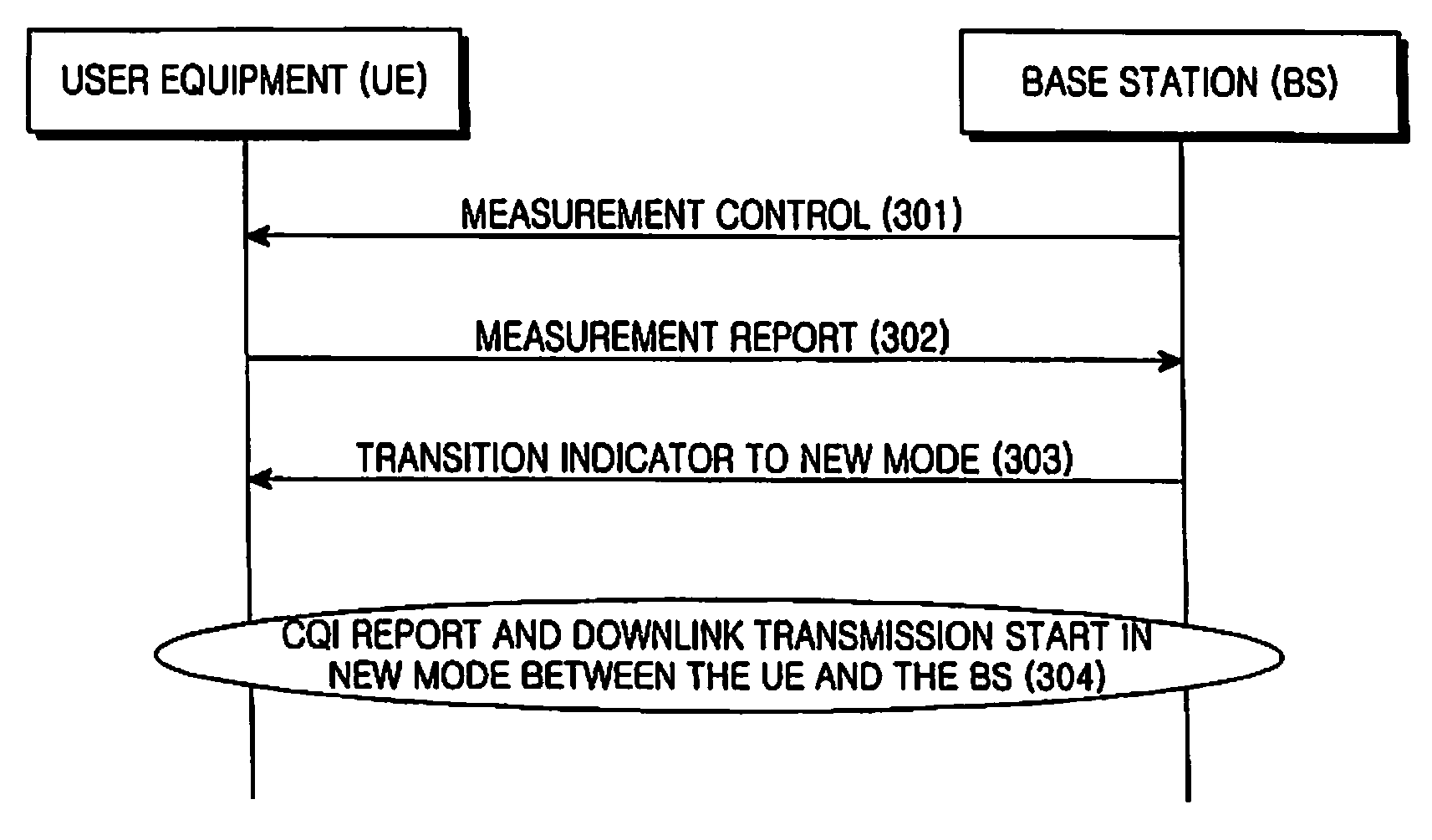
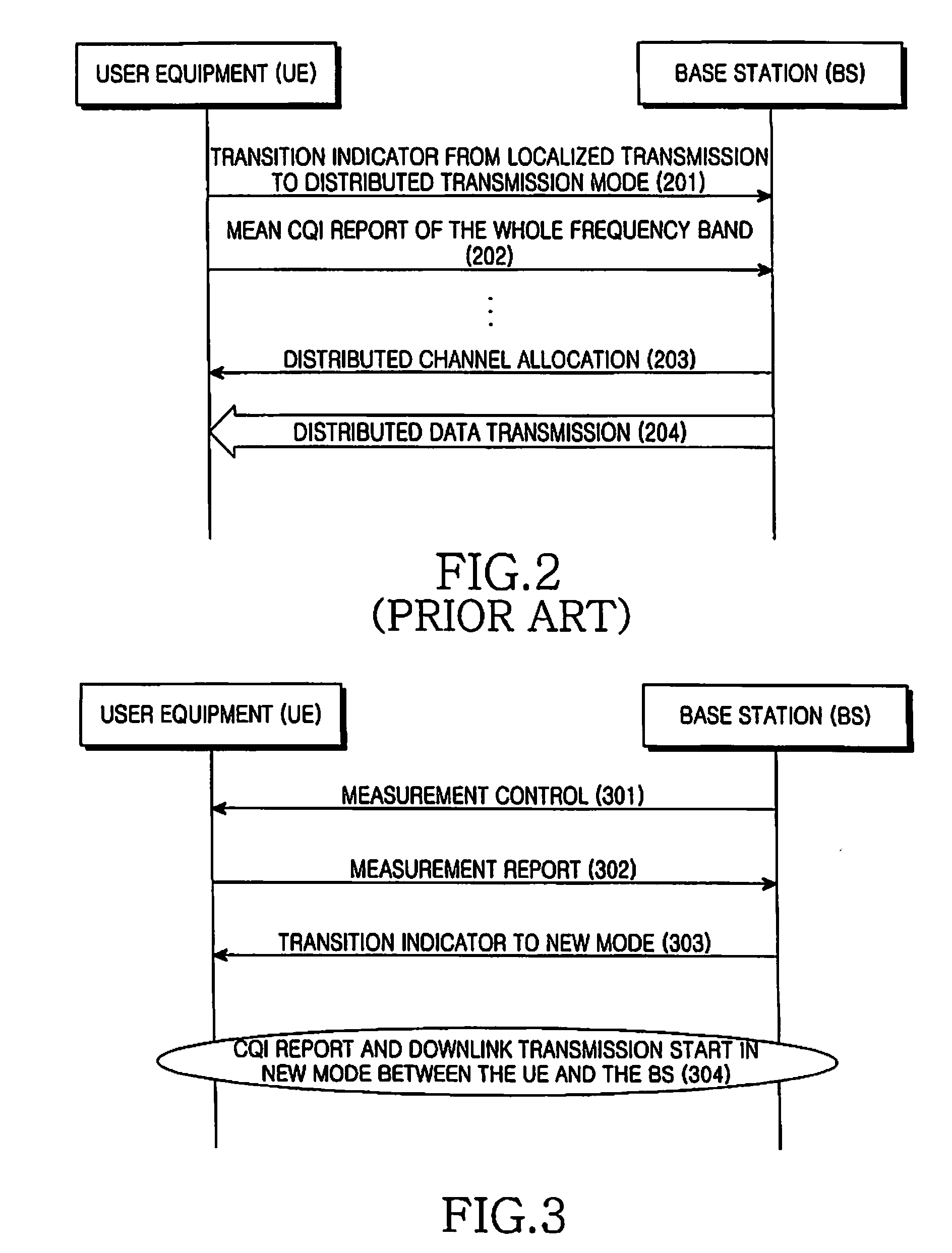
Provided is a method for transitioning between a distributed transmission mode and a localized transmission mode, including transmitting, by a Base Station (BS), a measurement control message to a User Element (UE), wherein the UE makes corresponding measurement and transmits a required measurement report message to the BS and the BS transmits a transition indicator message of new mode to the UE based on measurement report message sent from the UE; and commencing CQI reporting and a downlink transmission of a new mode between the UE and the BS. The BS can choose a more appropriate transmission mode for the downlink transmission based on changing characteristics of the channel in the time domain and the frequency domain.

Description

FIELD OF THE INVENTION[0001]The present invention relates to radio communication system with localized data transmission mode and distributed data transmission mode, especially to the transition between the two transmission modes.DESCRIPTION OF THE PRIOR ART[0002]Now, the 3rd Generation Mobile Communication System Partnership Project (referred to as 3GPP) standardization organization has commenced on Long-term Evolution (referred to as LTE) to existing system criteria. Among numerous physical layer transmission techniques, OFDM (Orthogonal Frequency Division Multiplex) becomes a challenging one in all downlink solutions, for it bears such advantages as higher spectrum efficiency and lower processing complexity.[0003]In nature, OFDM is a kind of multi-carrier modulation communication technique. Its basic principle is to divide a high rate data stream into multiple low rate data streams to transmit via a group of orthogonal sub-carriers simultaneously. Because of the nature of multi-c...

Claims


Application Information

Patent Timeline
IPC IPC(8): H04B17/00
CPCH04L27/2608H04L1/0001H04L5/0044H04L1/0025H04L1/0026
Inventor LEE, JU-HOLI, XIAOQIANGSUN, CHENGJUNSUN, CHUNYINGZHANG, YUJIAN
Owner SAMSUNG ELECTRONICS CO LTD
Learn More