
Method and system for lna adjustment to compensate for dynamic impedance matching

a dynamic impedance matching and adjustment method technology, applied in the field of wireless communication, can solve the problems of imposing certain operation restrictions and/or design challenges, requiring significant processing overhead, and incorporating multiple wireless communication technologies into devices such as wireless handsets. cost and complexity

Inactive Publication Date: 2009-05-21
BROADCOM CORP
View PDF3 Cites 25 Cited by
  • Summary
  • Abstract
  • Description
  • Claims
  • Application Information

AI Technical Summary

Benefits of technology

[0007]A system and / or method is provided for LNA adjustment to compensate for dynamic impedance matching, substantially as shown in and / or described in connection with at least one of the figures, as set forth more completely in the claims.

Problems solved by technology

Although desirable to users, incorporating multiple wireless communication technologies into devices such as wireless handsets may pose problems in terms of cost and complexity.
Moreover, coordinating the reception and / or transmission of data to and / or from the portable electronic device may require significant processing overhead that may impose certain operation restrictions and / or design challenges.
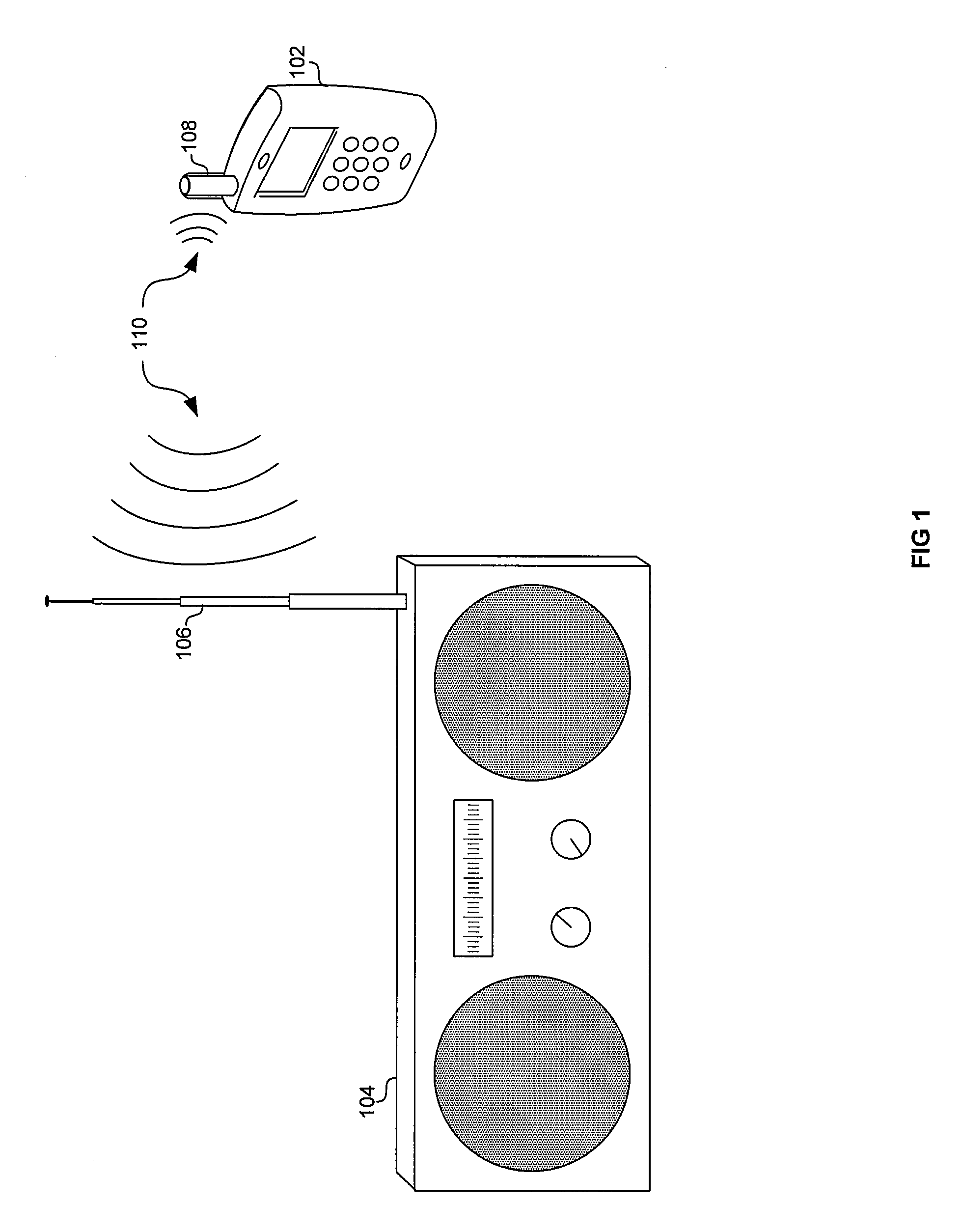
In this regard, conventional FM broadcast radios have relatively large antennas, which may not be practical for incorporating into a device such as a smart phone.
Accordingly, system designers are faced with the challenge of receiving a relatively broad FM broadcast band utilizing an antenna which is electrically very small.
In this regard, it may be difficult to reliably and / or consistently match an FM broadcast radio to a relatively small antenna as is typically found in a portable wireless device.
Furthermore, the frequency response of such an electrically small antenna may be incapable and or inefficient at receiving a broad frequency band, such. as the FM broadcast band.

Method used


Image

  • Method and system for lna adjustment to compensate for dynamic impedance matching
  • Method and system for lna adjustment to compensate for dynamic impedance matching
  • Method and system for lna adjustment to compensate for dynamic impedance matching

Examples


Embodiment Construction

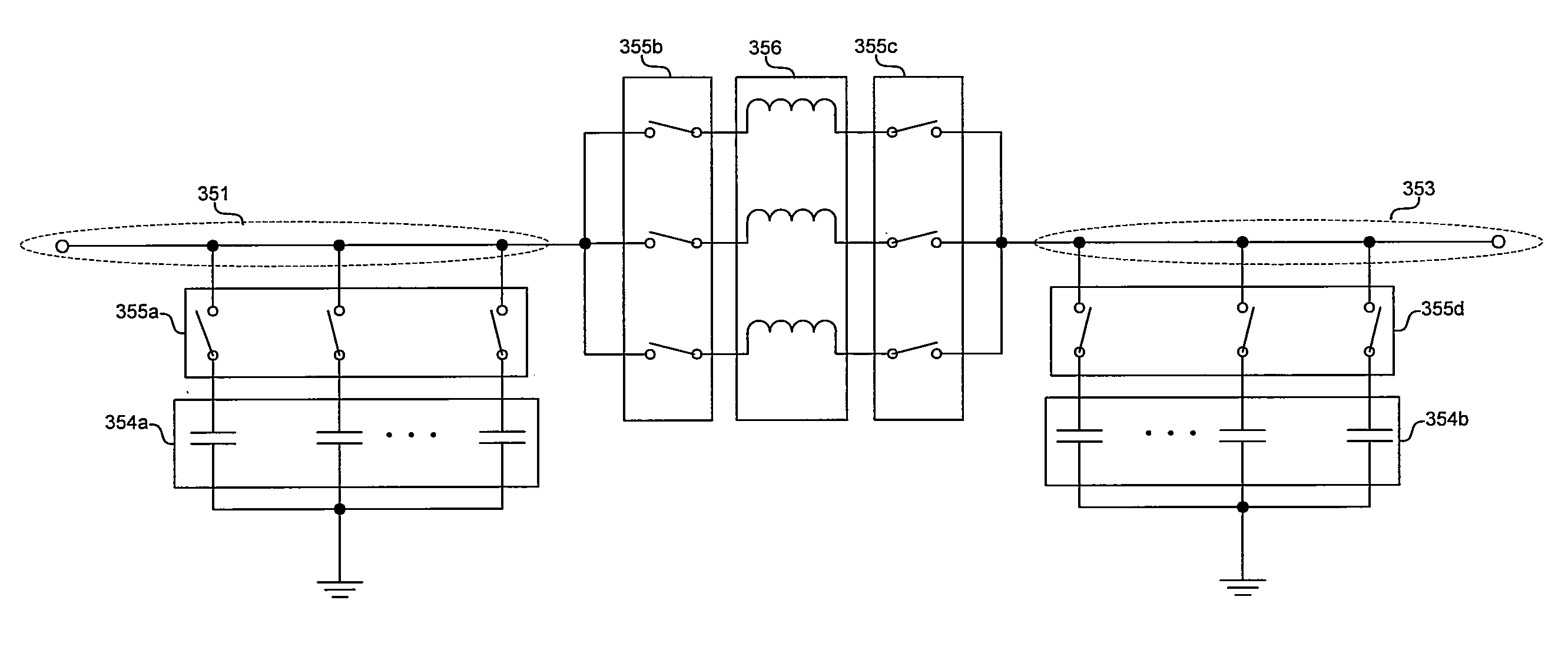
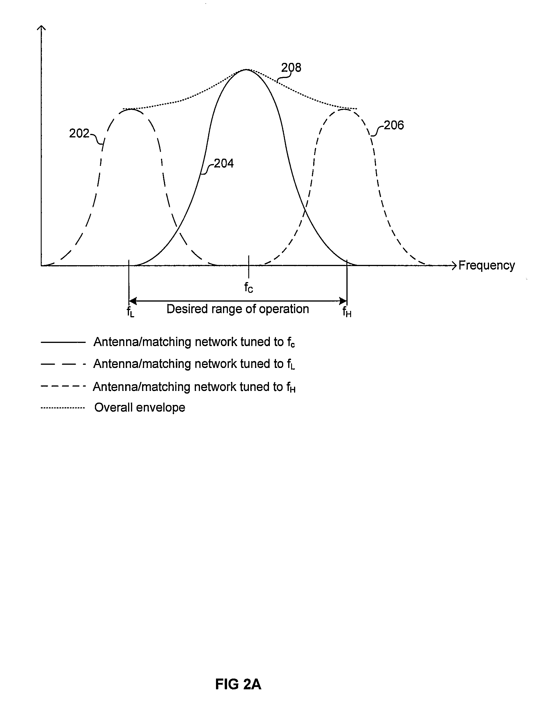
[0016]Certain embodiments of the invention may be found in a method and system for LNA adjustment to compensate for dynamic impedance matching. In this regard, an antenna matching network may be configured to maximize received signal strength for a determined frequency and an amplifier gain may be adjusted based on the maximized signal strength such that output levels of the amplifier are between specified limits. The antenna matching network may be programmatically controlled via one or more switching elements. The amplifier gain may be programmatically controlled via one or more bias points. The antenna matching network may be configured for a plurality of frequencies in a frequency band, such as an FM broadcast band, and a configuration for each frequency may be stored. Accordingly, when tuning the receiver to a frequency, a corresponding configuration may be retrieved from memory.

[0017]FIG. 1 depicts a conventional FM broadcast radio antenna in comparison to a smart phone antenn...


PUM


Abstract

Aspects of a method and system for LNA adjustment to compensate for dynamic impedance matching are provided. In this regard, an antenna matching network may be configured to maximize received signal strength for a determined frequency and an amplifier gain may be adjusted based on the maximized signal strength such that output levels of the amplifier are between specified limits. The antenna matching network may be programmatically controlled via one or more switching elements. The amplifier gain may be programmatically controlled via one or more bias points. The antenna matching network may be configured for a plurality of frequencies in a frequency band, such as an FM broadcast band, and a configuration for each frequency may be stored. Accordingly, when the receiver is tuned to a frequency, a corresponding configuration may be retrieved from memory.

Description

CROSS-REFERENCE TO RELATED APPLICATIONS / INCORPORATION BY REFERENCE[0001]Not ApplicableFIELD OF THE INVENTION[0002]Certain embodiments of the invention relate to wireless communications. More specifically, certain embodiments of the invention relate to a method and system for LNA adjustment to compensate for dynamic impedance matching.BACKGROUND OF THE INVENTION[0003]With the increasing popularity of various wireless standards and technologies, there is a growing demand to provide a simple and complete solution for wireless communications applications. In this regard, electronics manufacturers are increasingly attempting to incorporate multiple wireless technologies into portable electronic devices. For example, wireless technologies that are seeing widespread deployment include FM radio, Bluetooth (BT), GPS, Wi-Fi, and RFID.[0004]Although desirable to users, incorporating multiple wireless communication technologies into devices such as wireless handsets may pose problems in terms o...

Claims


Application Information

Patent Timeline
Patent Type & Authority Applications(United States)
IPC IPC(8): H03H7/38H01Q1/24
CPCH04B1/18H03H7/38H03H7/40
Inventor ROFOUGARAN, AHMADREZAROFOUGARAN, MARYAM
Owner BROADCOM CORP
Learn More