
Clutch control system for transmission

Active Publication Date: 2009-05-21
HONDA MOTOR CO LTD
View PDF5 Cites 6 Cited by
  • Summary
  • Abstract
  • Description
  • Claims
  • Application Information

AI Technical Summary

Benefits of technology

[0010]The present invention has been made for solving the above-mentioned problems in the prior art. Accordingly, it is an object of an embodiment of the present invention to provide a clutch control system for a transmission which is capable of appropriately performing preparations for the driving of a plurality of clutches driven by oil pressures supplied from a hydraulic pump, at an engine starting time.
[0018]According to an embodiment of the present invention, upon detection of the starting operation of the engine the control unit performs the initial preparatory operation for making preparations for the driving of the hydraulic clutches by generating predetermined oil pressures in the oil passages, and the initial preparatory operation is carried out by supplying the oil pressures into the oil passages at different timings. Therefore, the situation where the oil pressures are supplied into the oil passages at the same timing and an oil quantity in excess of the capacity of the hydraulic pump is needed is obviated in performing the initial preparatory operation, and the initial preparatory operation for the clutches can be carried out smoothly. This makes it possible to prevent an operational delay in relation to a first clutch driving command after the starting of the engine, and to enhance the response in regard of initial operations of the clutches. In addition, since it is unnecessary to supply the oil passages with the oil pressures at the same timing, the capacity of the hydraulic pump can be suppressed to a low level, and a smaller-sized transmission can be contrived. Further, by arbitrarily selecting the sequence in which the oil pressures are supplied at the time of the initial preparatory operation, the preparation for driving of an arbitrary one of the clutches can be started earlier than that of the other clutch.
[0021]According to an embodiment of the present invention, the transmission has a plurality of gear pairs between a main shaft and a counter shaft; the clutch on one side and the clutch on the other side are disposed on the main shaft and are operative to make and break the transmission of a rotational driving force between the engine and the transmission. The main shaft includes an inner pipe for supporting odd-ordinal speed gears, and an outer pipe for supporting even-ordinal speed gears. The clutch on one side makes and breaks transmission of the rotational driving force to the inner pipe and the clutch on the other side makes and breaks the transmission of the rotational driving force to the outer pipe. Therefore, in the twin-clutch type transmission in which the clutch on one side is in charge of odd-ordinal gear speeds and the clutch on the other side is in charge of even-ordinal gear speeds, the preparation for driving of the clutch on one side is completed early. This makes it possible to shorten the period of time necessary for the first speed gear, which is highly possibly used first after the starting of the engine, to be made usable.
[0022]According to an embodiment of the present invention, the clutch on one side supports at least a first speed gear serving as a lowest speed gear. Therefore, the period of time necessary for the lowest speed gear, which is highly frequently used at the time of vehicle starting, to be made usable is shortened, and a speedy vehicle starting after the starting of the engine can be achieved.
[0023]According to an embodiment of the present invention, a pipeline is connected to the hydraulic pump and a valve is connected to the oil passage on one side and the oil passage on the other side. The valve is so configured that the destination of supply of the oil pressure generated in the hydraulic pump is changed over between the hydraulic pump and the oil passage on one side or the other side, based on a command from the control unit. Therefore, in the transmission of the system in which the destination of supply of the oil pressure is selectively changed over between two clutches, the initial preparatory operation for the clutches can be carried out smoothly.

Problems solved by technology

In such a hydraulic type clutch, when the supply of the oil pressure is stopped attendantly on stopping of the engine, a working oil filling up an oil passage for the purpose of transmitting the oil pressure may be lost little by little from the oil passage due to leakage through gaps present in lubricated parts, leakage from hydraulic devices, or the like.
As a result, at the time of first driving the clutch after the starting of the engine, an operational delay may be generated in relation to the driving command.
In the technology according to Japanese Patent Laid-Open No. 2001-141045, however, in order to fill up the oil passages connected to the plurality of clutches with the working oil, the respective times to supply the oil pressures into the oil passages are computed from pipeline volume, engine speed and oil temperature, so that a complicated control is needed.
This results in that the master oil pressure Pm is lowered, and, as shown in FIG. 5(b), actual oil pressures generated at CL1 and CL2 do not conform to the target oil pressure, and the preparations for driving of the clutches are not carried out smoothly.
In addition, although the lowering of the master oil pressure Pm can be prevented if the capacity of the hydraulic pump is increased sufficiently, it is undesirable to enlarge the hydraulic pump in order to secure the capacity that is needed only for the preparations for driving of the clutches.

Method used


Image

  • Clutch control system for transmission
  • Clutch control system for transmission
  • Clutch control system for transmission

Examples


Embodiment Construction

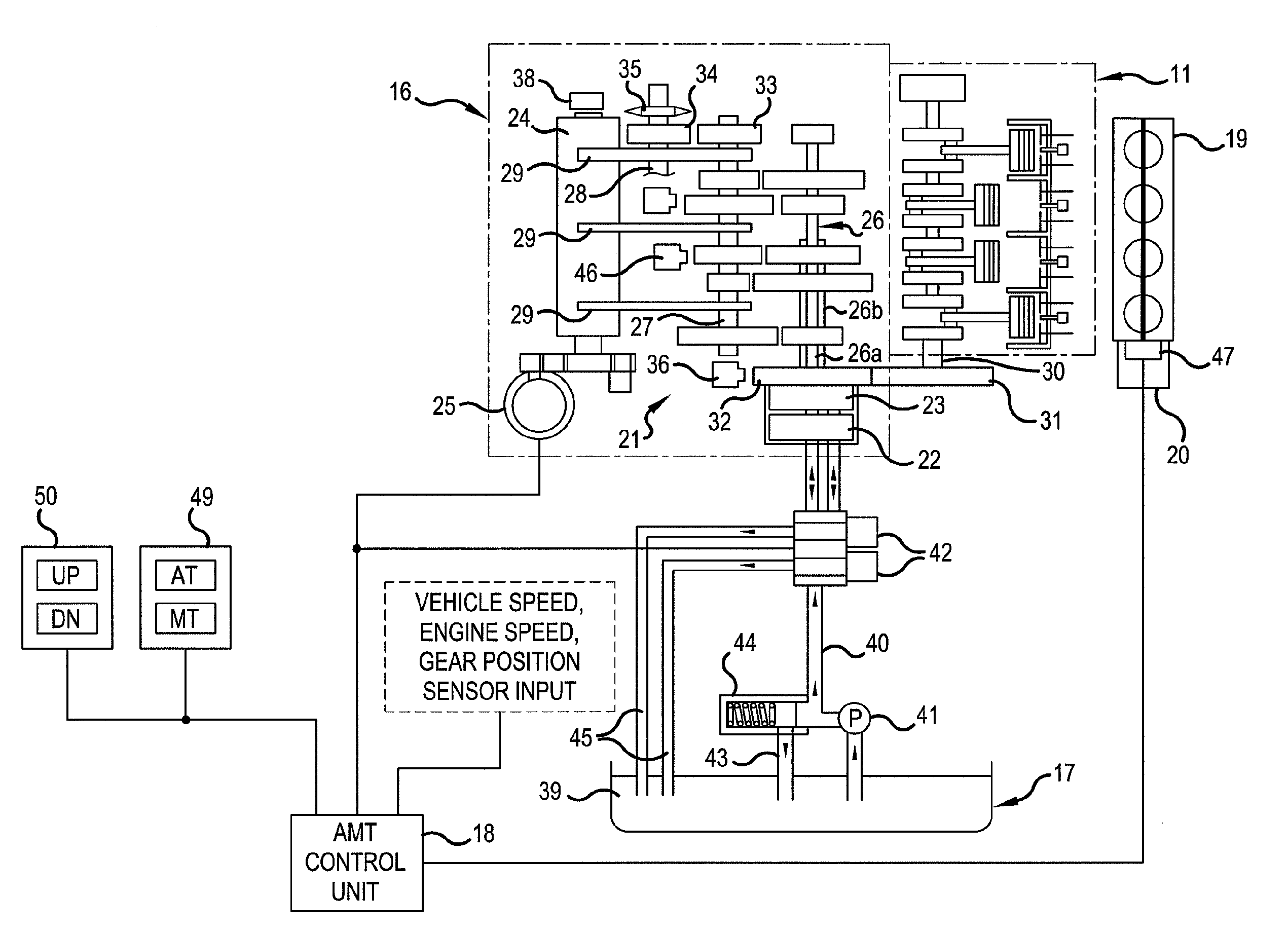
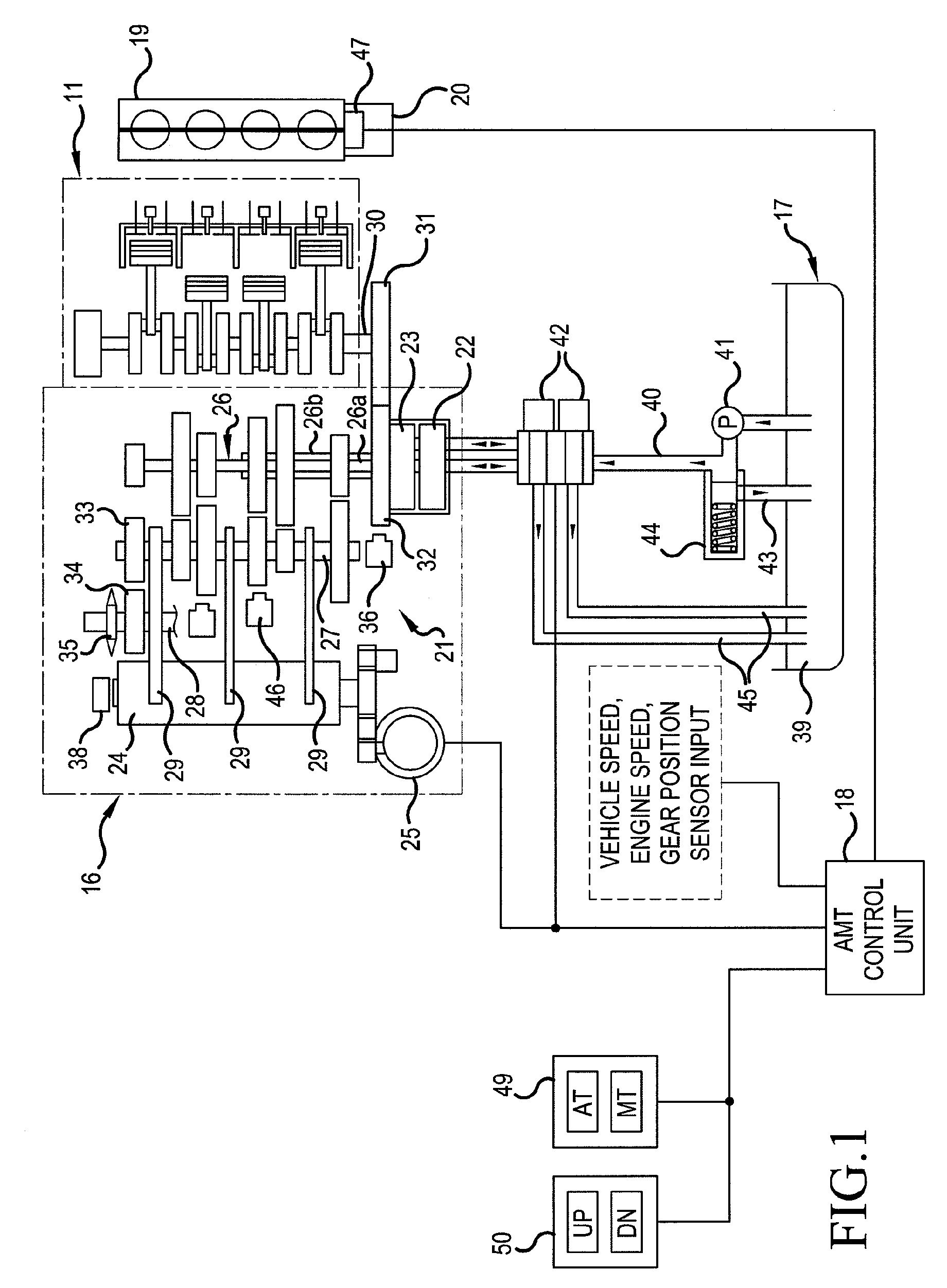
[0032]Now, a preferred embodiment of the present invention will be described below, referring to the drawings. FIG. 1 is a system block diagram of an automatic / manual transmission (hereinafter referred to as AMT) as an automatic transmission applied to a motorcycle and peripheral devices for the transmission. The AMT 16 connected to an engine 11 is controlledly driven by a clutch hydraulic system 17 and an AMT control unit 18 as a transmission controller. The engine 11 has a throttle-by-wire type throttle body 19, and the throttle body 19 is provided with a motor 20 for opening and closing the throttle.

[0033]The AMT 16 includes transmission gears 21 for a multiplicity of gear speeds, a first clutch 22, a second clutch 23, a shift drum 24, and a shift control motor 25 for turning the shift drum 24. A multiplicity of gears constituting the transmission gears 21 are respectively connected to or loosely fitted over a main shaft 26, a counter shaft 27, and a transmission gear output shaf...


PUM


Abstract

A clutch control system for a twin-clutch type automatic / manual transmission AMT includes a hydraulic pump for driving a first clutch and a second clutch and oil passages for transmitting oil pressures and an AMT control unit for controlling the supply of oil pressures into the oil passages. Upon detection of an engine starting operation, the AMT control unit performs an initial preparatory operation in which the oil pressures are supplied into the oil passages at different timings so as to fill up the oil passages with a working oil, thereby completing the preparations for driving of the clutches. When the oil pressure is supplied into the oil passage after a predetermined oil pressure is generated in the oil passage, the period of time taken for a first speed gear to become usable is shortened, whereby a swift vehicle starting after the starting of the engine can be achieved.

Description

CROSS-REFERENCE TO RELATED APPLICATIONS[0001]The present application claims priority under 35 USC 119 to Japanese Patent Application No. 2007-301586 filed on Nov. 21, 2007 the entire contents of which are hereby incorporated by reference.BACKGROUND OF THE INVENTION[0002]1. Field of the Invention[0003]The present invention relates to a clutch control system for a transmission. More particularly, to a clutch control system for a transmission which can appropriately perform preparations for driving a plurality of hydraulic clutches driven by oil pressures supplied from a hydraulic pump, at an engine starting time.[0004]2. Description of Background Art[0005]Hitherto, there has been known a transmission which has a hydraulic pump driven attendantly on the rotation of a crankshaft and in which connection / disconnection of a clutch is controlled by an oil pressure generated by the hydraulic pump. In such a hydraulic type clutch, when the supply of the oil pressure is stopped attendantly on ...

Claims


Application Information

Patent Timeline
IPC IPC(8): F16H59/60
CPCF16D48/08Y10T477/753F16D2500/1086F16D2500/3067F16D2500/3069F16D2500/50224F16D2500/70217F16D2500/70412F16D2500/70414F16H61/0021F16H61/688F16H2306/36F16H2312/14F16H2312/20Y10T477/78Y10T477/65F16D2500/1026
Inventor NEDACHI, YOSHIAKITSUKADA, YOSHIAKIOZEKI, TAKASHIKOJIMA, HIROYUKIFUKAYA, KAZUYUKI
Owner HONDA MOTOR CO LTD
Features
  • Generate Ideas
  • Intellectual Property
  • Life Sciences
  • Materials
  • Tech Scout
  • Unparalleled Data Quality
  • Higher Quality Content
  • 60% Fewer Hallucinations
Learn More