
Bone screw and method for manfacturing the same

a bone screw and screw body technology, applied in the field of bone screw, can solve the problems of screw loosening or “backing out”, bone mis-setting, and high torque required between the screw and the bone to penetrate the bone for proper application, and achieve the effect of reducing the torque required, reducing the rate of osteoporotic bone splitting, and reducing the friction between the screw and the bon

Active Publication Date: 2009-05-21
MEDICAL FACETAB
View PDF15 Cites 16 Cited by
  • Summary
  • Abstract
  • Description
  • Claims
  • Application Information

AI Technical Summary

Benefits of technology

[0008]The faceted bone screw of the present principles will operate to reduce the friction between the screw and the bone, thereby reducing the torque required to drive the screw and / or threaded pins into the bone. This torque reduction can thereby assist in lowering the rate of splitting osteoporotic bone particularly around the shaft of the screw while the bone screw is inserted.
[0009]The faceted bone screw of the present principles will also reduce the likelihood of bone screws and threaded pins backing out of the bone due to improved osteointegration between the faceted threaded portion of the implanted device and the bone.
[0011]According to another implementation, the method of manufacturing an orthopedic screw includes loading a bar stock into a bar feeder, selecting a guide bushing having a desired clearance related harmonic level. The harmonic level being configured to impart a controlled milling effect to the loaded bar stock. A circular threading tool is then selected and installed corresponding to the desired thread configuration. The bar stock is then cut at the desired harmonic level using the circular threading tool to produce a faceted thread milled into at least a portion of the bar stock under the controlled milling effect of the guide bushing.

Problems solved by technology

Splitting often occurs when the workpiece (e.g., bone) is brittle by nature, and the friction between the screw and the bone requires higher torques to sufficiently penetrate the bone for proper application.
Another concern is the potential for the screws to loosen or “back out” after installation.
This loosening can result in the mis-setting of a bone and require supplemental procedures to be performed to correct the same.

Method used


Image

  • Bone screw and method for manfacturing the same
  • Bone screw and method for manfacturing the same
  • Bone screw and method for manfacturing the same

Examples


Embodiment Construction

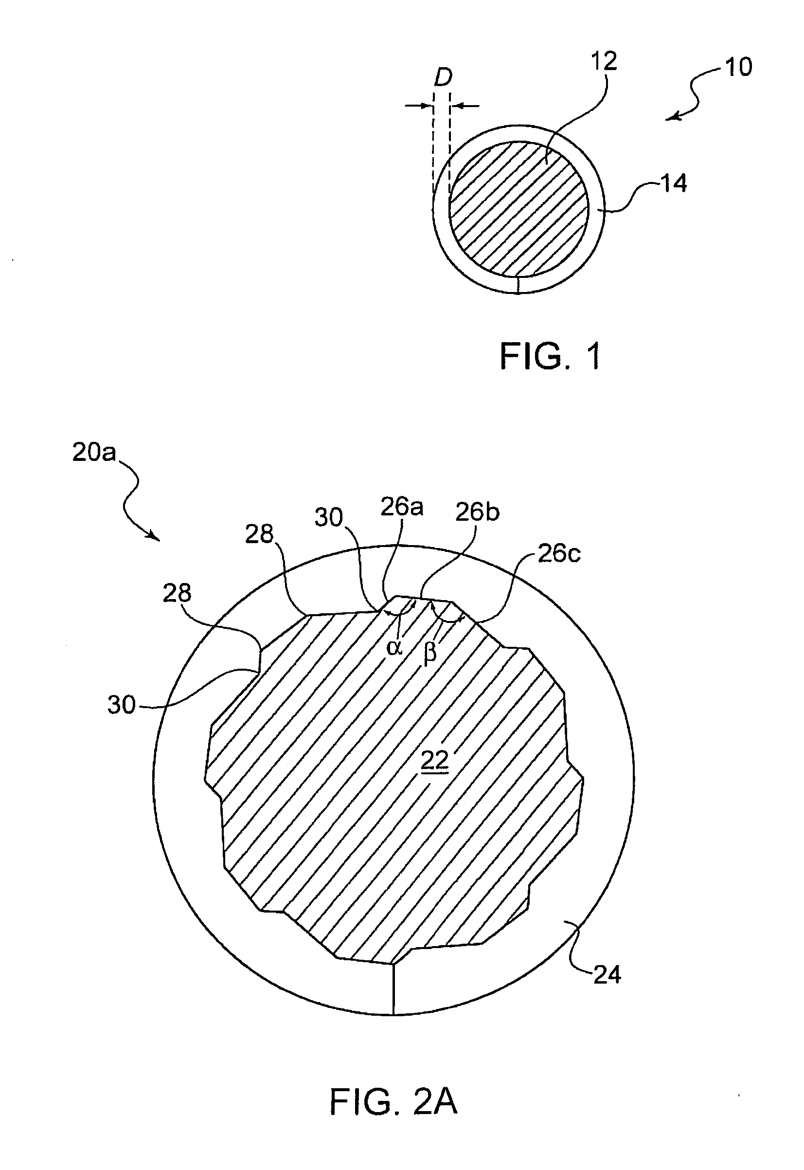
[0020]FIG. 1 shows a cross section of a bone screw 10 according to the prior art. The shaft 12 includes a thread 14 that can extend any length of the shaft 12, including the entire length of the same. The thread generally has a consistent non-variable depth D depending on the particular application for that screw. The pitch, which relates to the distance between adjacent threads, is also generally consistent for most bone screws and fasteners.

[0021]Those of ordinary skill in the art will recognize that one or more different portions of the shaft 12 can include threads 14, or alternatively the entire shaft 12 can be threaded. These same concepts apply to the bone screw of the present principles.

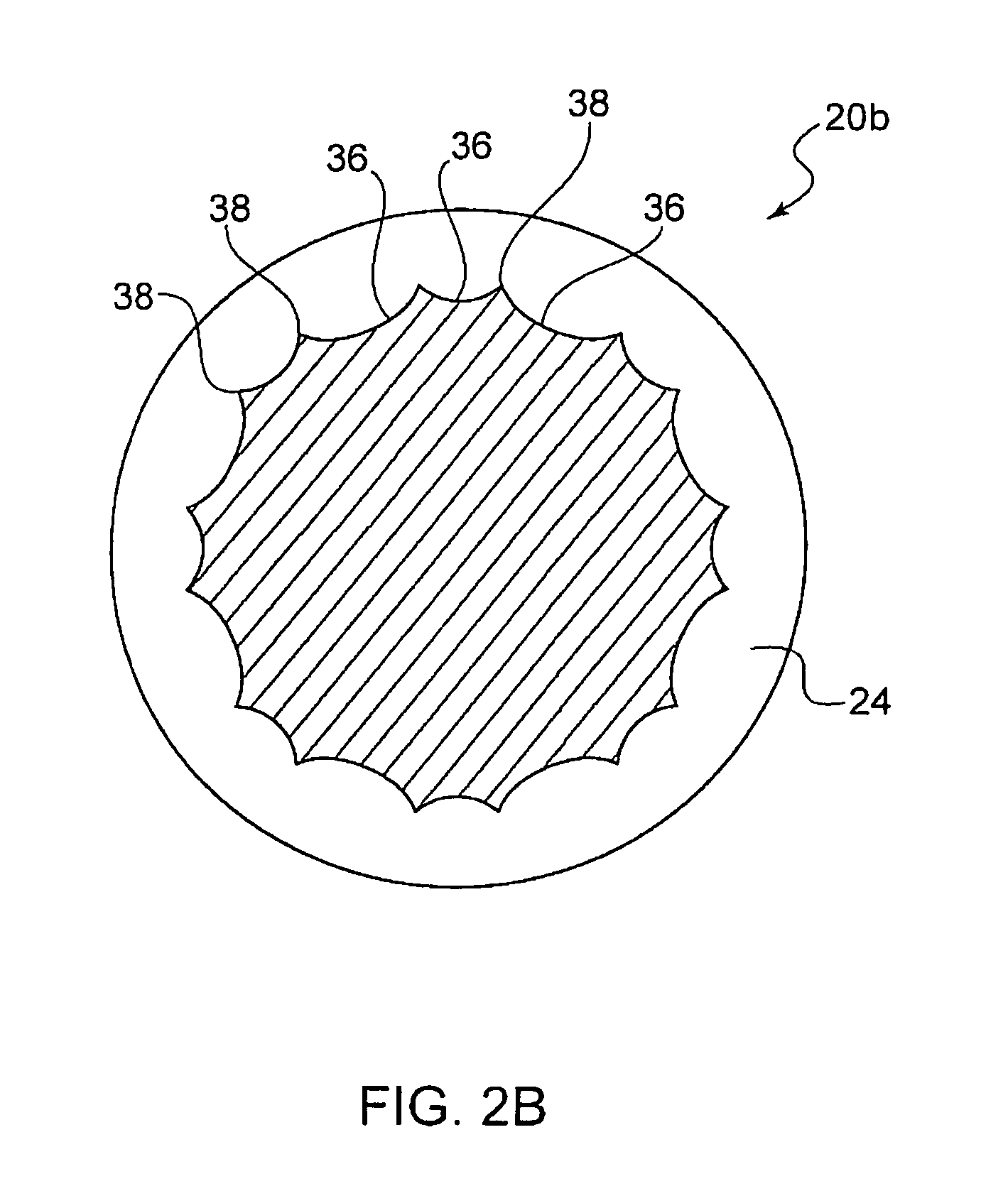
[0022]FIG. 2 shows a cross section of a faceted bone screw 20 according to an implementation of the present principles. The bone screw 20 has a shaft 22 having threads 24 which include one or more facets 26a, 26b and 26c. These facets are generally transverse to the thread groove and extend ac...


PUM

PropertyMeasurementUnit
Lengthaaaaaaaaaa
Dimensionaaaaaaaaaa
Depthaaaaaaaaaa

Abstract

A faceted bone screw and a method for manufacturing the same includes a screw thread configuration having facets that are substantially transverse to the thread. The facets are generally made up of a plurality of transitioning peaks and valleys which vary the depth of the thread and are disposed in one or more locations throughout the threaded portion of the bone screw. The facets operate to reduce the torque required to drive the bone screw into bone, while at the same time operate to assist in anchoring the bone screw within the bone once inserted therein, and thereby reduce the possibility for the screw backing out after insertion.

Description

BACKGROUND[0001]1. Technical Field[0002]The present principles relate to orthopedic (bone) screws. More particularly, it relates to a faceted orthopedic screw and method for making the same.[0003]2. Description of Related Art[0004]Medical screws or Orthopedic (bone) screws or threaded pins are commonly used in orthopedic procedures where it is required to set a bone or multiple bones in a position that is secure with respect to either 1) the adjacent bone or bone part for which the screw is used; or 2) the surgical splint or other external fixation device that is maintained in position using the bone or orthopedic screw. As used herein, the term “bone screw” and / or “orthopedic screw” are interchangeably used herein and shall include all known medical and orthopedic screws and threaded pins that are used human and / or animal bones.[0005]One common concern in the use of bone screws is the splitting of the bone during the insertion of the screw. Splitting often occurs when the workpiece...

Claims


Application Information

Patent Timeline
IPC IPC(8): A61B17/04A61B17/56B23D1/00B23P13/04B23D41/04
CPCA61B17/8625B23G9/001Y10T409/505904Y10T29/49995Y10T409/40735A61B17/866
Inventor WILLERT, WAYNE A.RUPP, GLENN A.LOVELL, KEVIN J.
Owner MEDICAL FACETAB
Learn More