Flight Control System

a technology of flight control system and aircraft, which is applied in the direction of vehicle position/course/altitude control, process and machine control, instruments, etc., can solve the problems of extreme changes in attitude, extreme deviation of flight path from intended flight path, and easy disturbance of the altitude of unmanned helicopters

Inactive Publication Date: 2009-05-21
YAMAHA MOTOR CO LTD
View PDF1 Cites 105 Cited by
  • Summary
  • Abstract
  • Description
  • Claims
  • Application Information

AI Technical Summary

Benefits of technology

[0014]In view of the circumstances noted above, an aspect of the least one of the embodiments disclosed herein is to provide a flight control system in which it is easy to view data transmitted from the airframe and the payload device of the aircraft and an operation panel for making a control of the airframe and the payload device.

Problems solved by technology

Characteristically, an attitude of an unmanned helicopter is easily disturbed by wind.
Further, structural features of such an unmanned helicopter result in extreme changes in attitude during a flight, for example, while a turn is made.
If an unmanned helicopter of such a type is, for example, caught in a strong crosswind, the flight path may extremely diverge from an intended flight path.
An autonomous control can also take a long time to correct a flight path.
Consequently, such continuous monitoring can be taxing on the operator when the helicopter is operated for a long time.
This is because it is extremely complex work to make an appropriate control by understanding the status of the airframe and flight and a state of the payload described above while watching a large amount of data.

Method used


Image

  • Flight Control System
  • Flight Control System
  • Flight Control System

Examples


Embodiment Construction

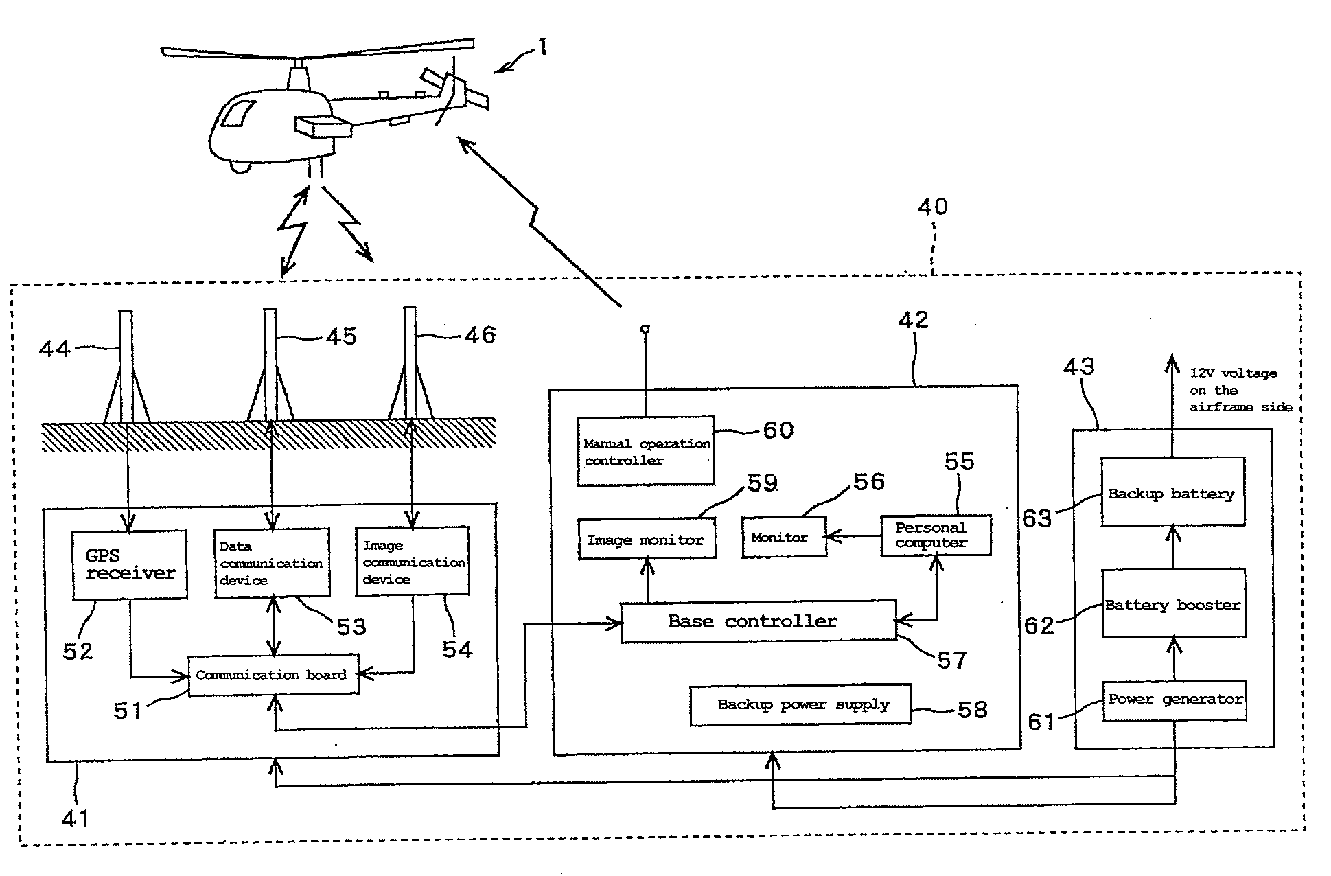
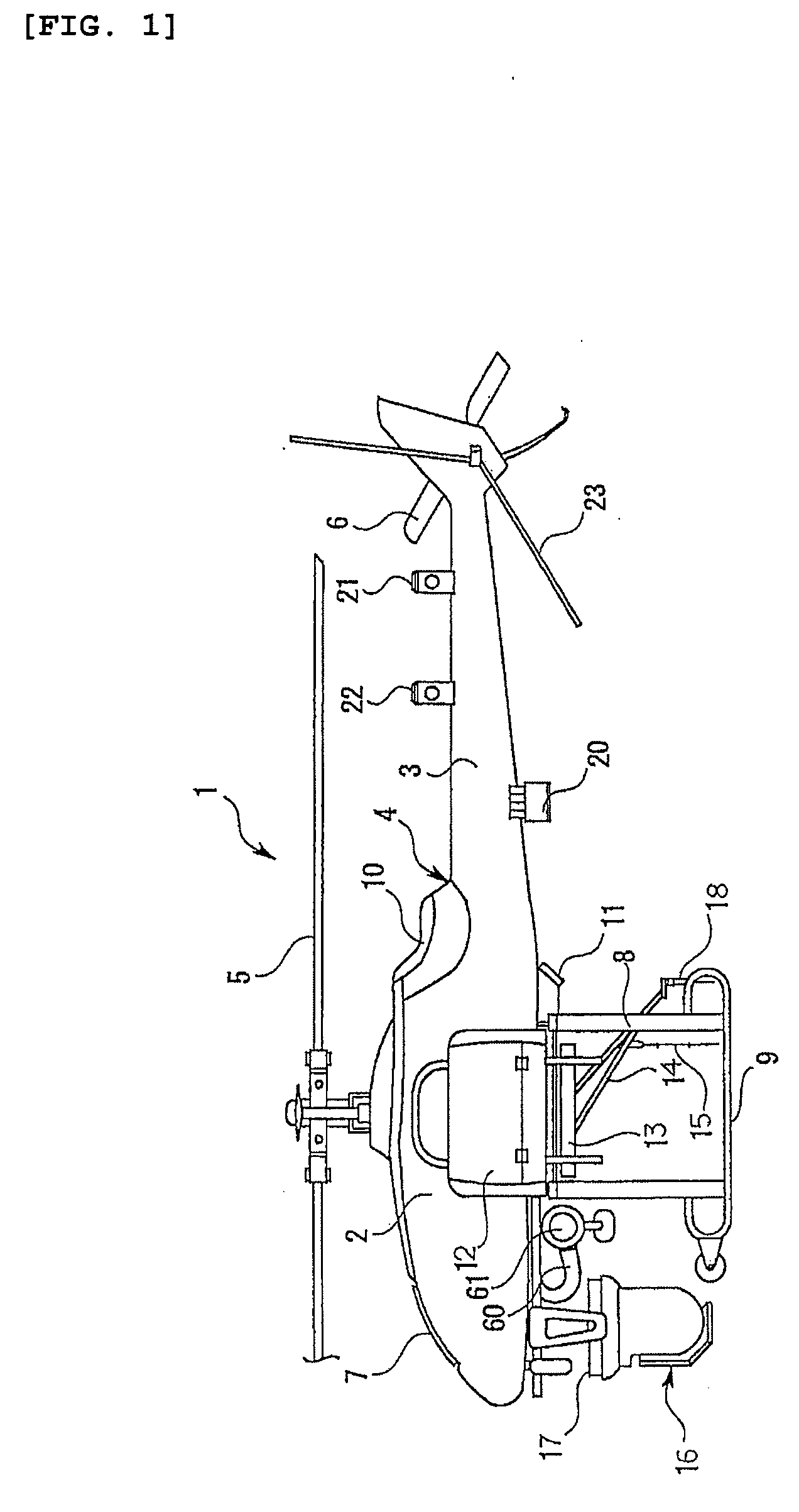
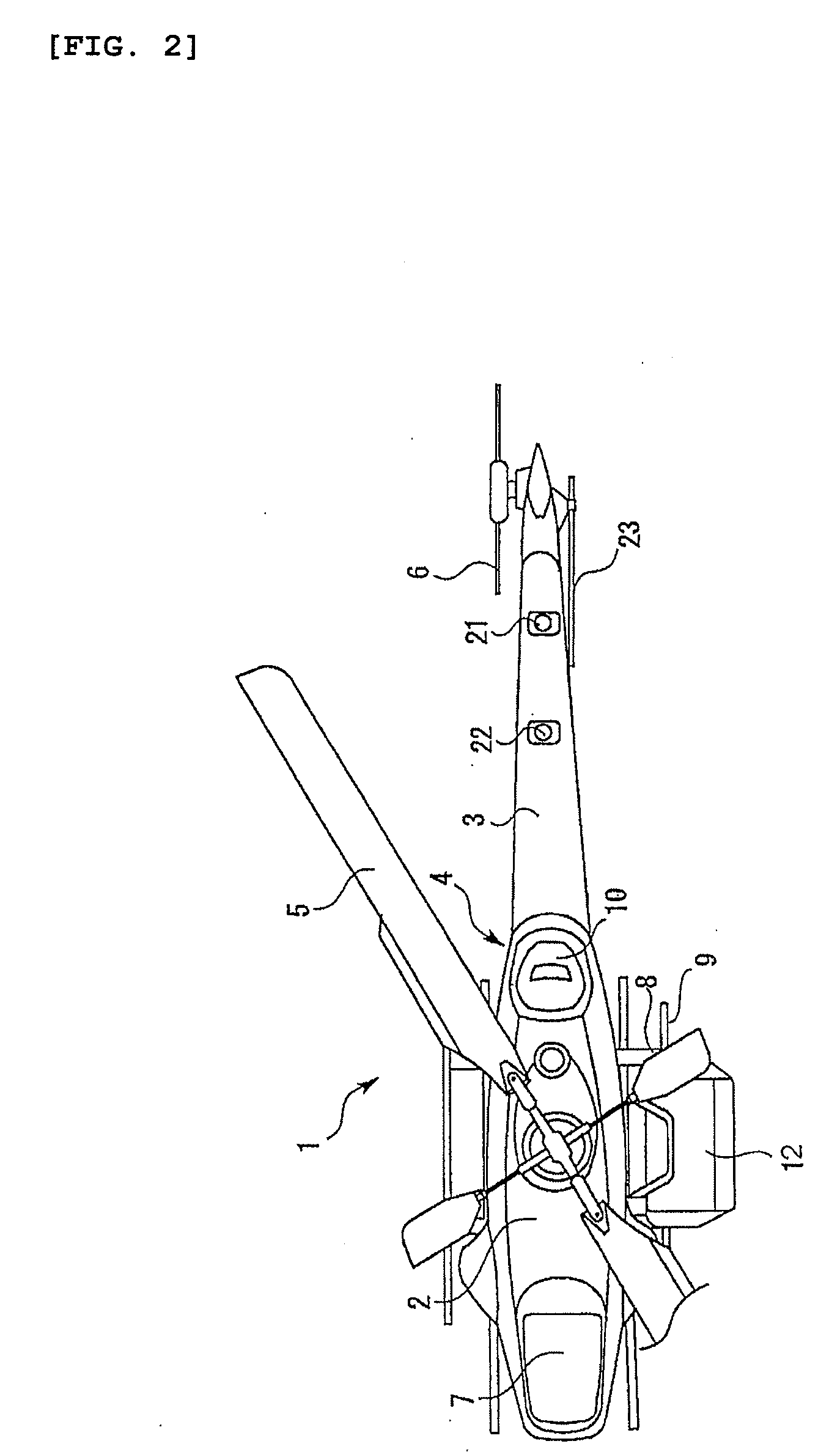
[0023]An embodiment of a flight control system will be described in detail hereinafter with reference to FIGS. 1 to 6. FIGS. 1 to 3 show a helicopter as an example of an aircraft according to the present invention, illustrating an unmanned helicopter provided with a camera device for recording an aerial photograph. FIG. 1 shows a side view, FIG. 2 shows a top view, and FIG. 3 shows a front view.

[0024]A helicopter 1 has an airframe 4 including a main body 2 and a tail body 3. A main rotor 5 is provided on the upper part of the main body 2, while a tail rotor 6 is provided on the rear part of the tail body 3. A radiator 7 is provided on the front part of the main body 2, behind which an engine, an intake system, a main rotor shaft, and a fuel tank are housed in this order in the main body 2. The fuel tank with a large capacity is housed in the vicinity of the center of the airframe in order to make an external sub-fuel tank unnecessary. A skid 9 is provided via a support leg 8 at the ...


PUM


Abstract

An aircraft (1) and a terrestrial station (40) for communicating with each other are provided. An airframe and a payload device of an aircraft is controlled from the terrestrial station. The aircraft (1) transmits data concerning a situation of the airframe, a situation of a flight, and a situation of the payload device to the terrestrial station (40). The terrestrial station (40) includes one monitor screen (56) for simultaneously displaying all the data transmitted from the aircraft and an operation panel.

Description

CROSS-REFERENCE TO RELATED APPLICATIONS[0001]This application is a U.S. National Phase of the International Application No. PCT / JP2006 / 305513 filed Mar. 20, 2006 designating the U.S. and published in Japanese on Sep. 21, 2006 as WO 2006 / 098469, which claims priority of Japanese Patent Application No. 2005-080773, filed Mar. 18, 2005.BACKGROUND OF THE INVENTION[0002]1. Technical Field[0003]The present invention relates to a flight control system of an aircraft and in particular relates to a flight control system of an aircraft for enabling communication between an unmanned helicopter and a terrestrial station for applying agrochemicals or the like or for mounting a camera device for recording a picture from the sky.[0004]2. Description of the Related Art[0005]Conventionally, a radio-controlled unmanned helicopter is used for applying agrochemicals from the sky or for recording aerial photographs or videos. As disclosed in Japanese Publication JP-A-2004-268737, for example, such a con...

Claims


Application Information

Patent Timeline
Patent Type & Authority Applications(United States)
IPC IPC(8): G05D1/00G08B23/00
CPCA01M7/0089B64C39/024B64C2201/024B64C2201/108G05D1/0094B64C2201/146G05D1/0038G05D1/0044B64C2201/127B64U10/10B64U30/20B64U2101/30B64U2201/20A01M7/00B64D43/00B64D47/08
Inventor SHIBATA, HIDEKI
Owner YAMAHA MOTOR CO LTD
Why Eureka
Try Eureka