

Acceleration measuring device
a measuring device and acceleration technology, applied in the direction of acceleration measurement in multiple dimensions, acceleration measurement using interia forces, instruments, etc., can solve the problems of difficult to obtain acceleration data at the stationary state, disadvantages of conventional acceleration measuring devices, and long time consumption, etc., to achieve the effect of quick estimate of offset or
- Summary
- Abstract
- Description
- Claims
- Application Information
AI Technical Summary
Benefits of technology
Problems solved by technology
Method used
Image

Examples
first embodiment
[0072]A first embodiment of the present invention is explained on the basis of FIG. 1.
[0073]Before explaining an acceleration measuring device according to the present invention in detail, in this embodiment, the basic structure of the acceleration measuring device is schematically explained.
[0074]
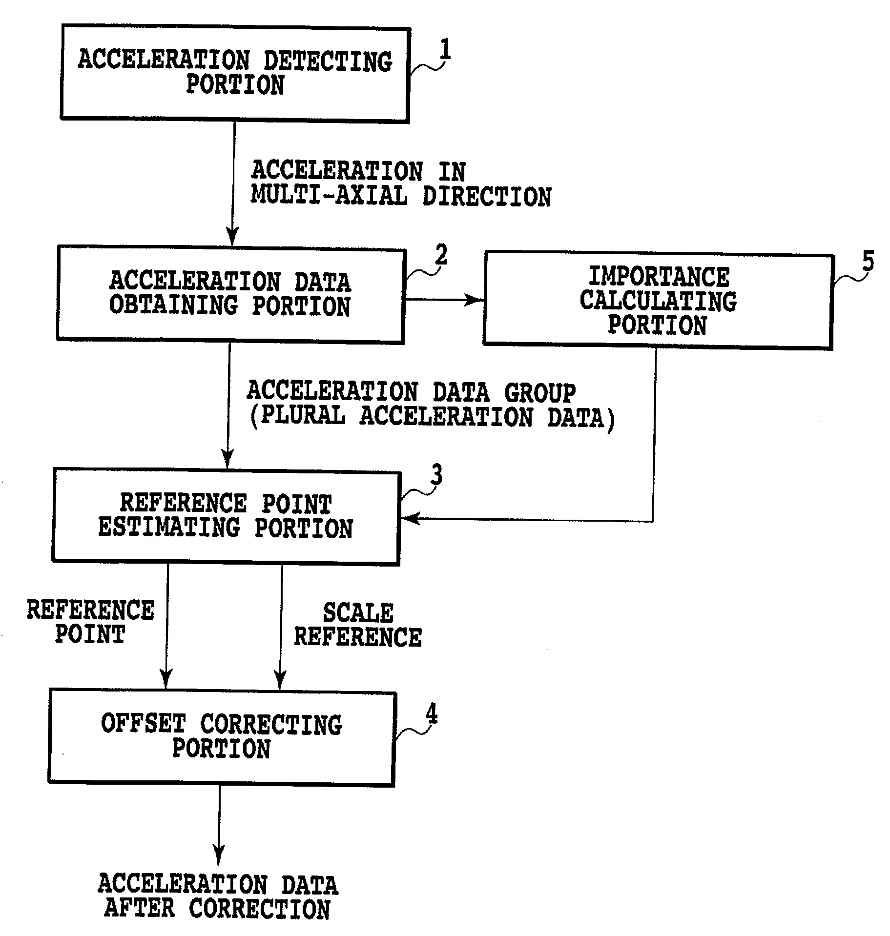
[0075]FIG. 1 shows the rough structure of the acceleration measuring device according to the present invention.
[0076]The acceleration measuring device includes an acceleration detecting portion 1, an acceleration data obtaining portion 2, an importance calculating portion 5, a reference point estimating portion 3, and an offset correcting portion 4.
[0077]
[0078]Basic operations of the acceleration measuring device are explained.
[0079]The acceleration detecting portion 1 detects accelerations in two-axis or three-axis directions.
[0080]The acceleration data obtaining portion 2 obtains the accelerations detected by the acceleration detecting portion 1 as acceleration data.
[0081]The reference p...
second embodiment
[0092]A second embodiment of the present invention is explained on the basis of FIGS. 2 to 4. Explanation of components same as those in the first embodiment is omitted and the components are denoted by the same reference numerals and signs.
[0093](Finite Data DOE)
[0094]
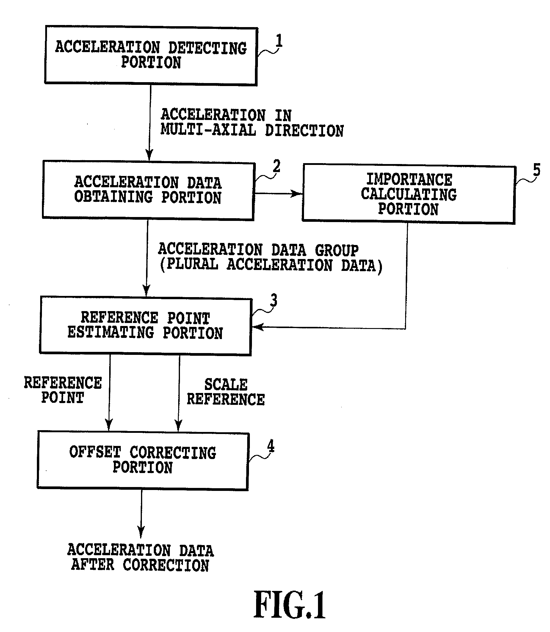
[0095]FIG. 2 shows an example of the structure of an acceleration measuring device according to the present invention.
[0096]The acceleration measuring device includes the acceleration detecting portion 1, the acceleration data obtaining portion 2, a finite data reference point estimating portion 10, and the offset correcting portion 4. In the following explanation, explanation concerning the components other than the finite data reference point estimating portion 10 is omitted.
[0097]The finite data reference point estimating portion 10 is explained.
[0098]The finite data reference point estimating portion 10 includes a representative data calculating portion 11, a first importance calculating portion 12, a data selecti...
third embodiment
[0174]A third embodiment of the present invention is explained on the basis of FIG. 5. Explanation of components same as those in the respective embodiments described above is omitted and the components are denoted by the same reference numerals and signs.
[0175](Infinite DOE)
[0176]
[0177]FIG. 5 shows an example of the structure of an acceleration measuring device according to the present invention.
[0178]The acceleration measuring device includes the acceleration detecting portion 1, the acceleration data obtaining portion 2, an infinite data reference point estimating portion 20, and the offset correcting portion 4. In the following explanation, explanation of the components other than the infinite data reference point estimating portion 20 is omitted.
[0179]The infinite data reference point estimating portion 20 is explained.
[0180]The infinite data reference point estimating portion 20 includes an importance calculating portion 21, a storing portion 22, and a second reference point e...
PUM
 Abstract
Description
Claims
Application Information