Cooling structure of cylinder head

a technology of cooling structure and cylinder head, which is applied in the direction of engine cooling apparatus, liquid cooling, cylinders, etc., can solve the problems of difficult cooling of coolant, inability to send coolant to the vicinity of the top of each of the combustion chambers, and insufficient cooling structure of the cooling structur

Inactive Publication Date: 2009-05-28
TOYOTA JIDOSHA KK
View PDF1 Cites 16 Cited by
  • Summary
  • Abstract
  • Description
  • Claims
  • Application Information

AI Technical Summary

Benefits of technology

[0005]Accordingly, it is an objective of the present invention to reliably cool a highly heated portion in the vicinity of a top of a combustion chamber by a cooling structure of a cylinder head having a coolant passage divided into an intake-side passage and an exhaust-side passage.

Problems solved by technology

However, the cooling structure does not appropriately send the coolant to the vicinity of the top of each of the combustion chambers, which are formed in the respective cylinders.
This makes it difficult for the coolant to cool, particularly, most heated portions such as a section between each adjacent pair of the exhaust ports, a section between each adjacent pair of the exhaust valves, and the proximity of the ignition plug of each of the cylinders.

Method used


Image

  • Cooling structure of cylinder head
  • Cooling structure of cylinder head
  • Cooling structure of cylinder head

Examples


Embodiment Construction

[0011]One embodiment of the present invention will now be described with reference to the attached drawings.

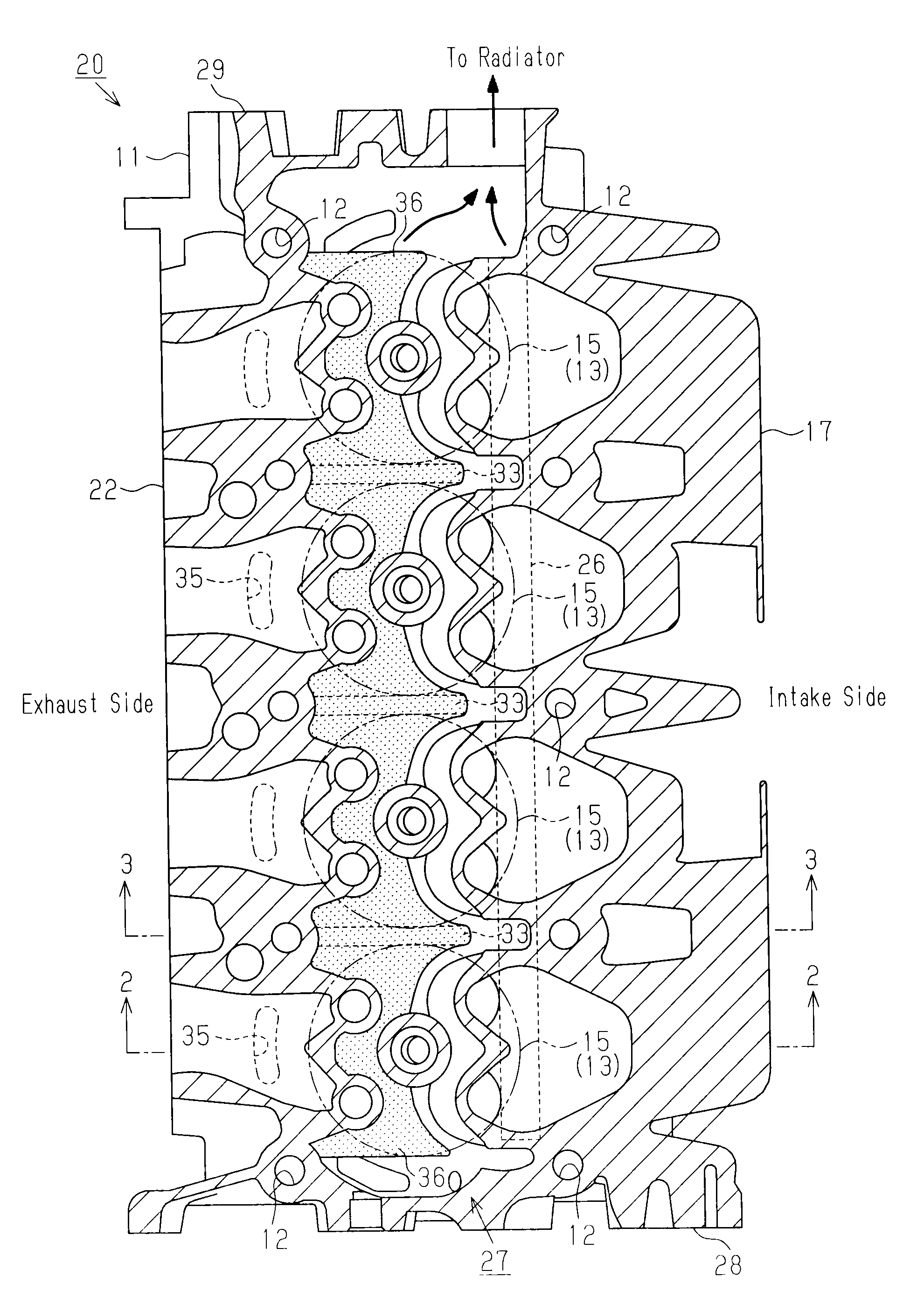
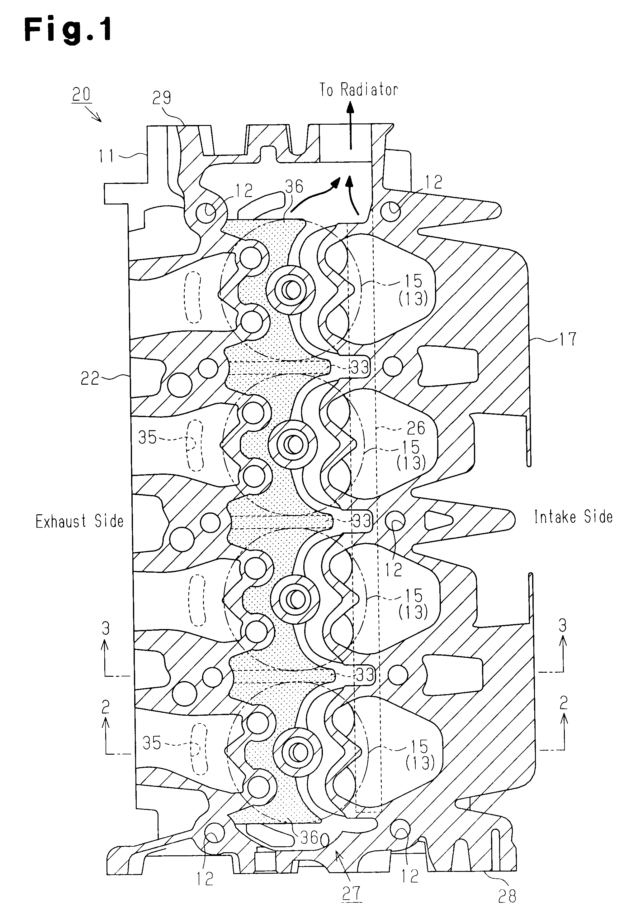
[0012]As shown in FIGS. 1 to 3, a gasoline engine (hereinafter, simply referred to as an engine) 20, which serves as an internal combustion engine, includes a cylinder block 10. A plurality of (in the illustrated embodiment, four) cylinders 15 are formed in the cylinder block 10 and arranged along a line. A cylinder head 11 is mounted on the cylinder block 10 and fastened to the cylinder block 10 by bolts (not shown) passed through a plurality of bolt holes 12.

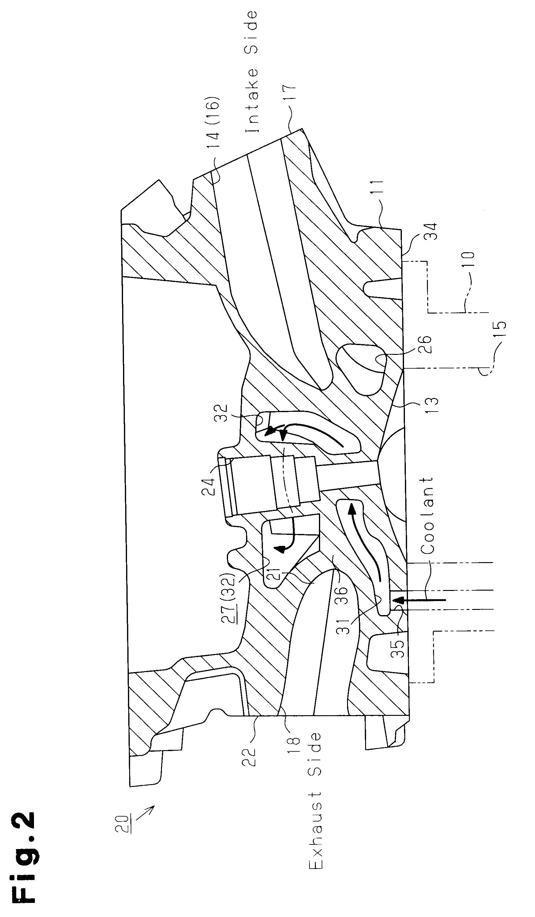
[0013]A combustion chamber 13 is formed in a bottom surface 34 of the cylinder head 11 at a position corresponding to each of the cylinders 15. With reference to FIGS. 2 to 4, a pair of intake ports 14, 14 through which intake air is fed to the corresponding one of the combustion chambers 13 are formed in the cylinder head 11 in correspondence with each of the cylinders 15. The intake ports 14, 14 corresponding to each c...


PUM


Abstract

A coolant passage in a cylinder head of a multi-cylinder internal combustion engine is divided into an intake-side passage below intake ports and extending in a cylinder arranging direction, and an exhaust-side passage including plural exhaust-side lateral passages corresponding to respective cylinders and an exhaust-side longitudinal passage. The exhaust-side lateral passages (1) are mutually separated by partition walls at a position corresponding to the section between a corresponding adjacent pair of the cylinders, (2) have an inlet for coolant in the vicinity of exhaust ports of a corresponding one of the cylinders, and (3) extend from the inlet toward the intake port via the vicinity of a top of a combustion chamber formed in the corresponding cylinder. The exhaust-side longitudinal passage extends along the cylinder arranging direction. Downstream ends of the exhaust-side lateral passages connect to the exhaust-side longitudinal passage.

Description

TECHNICAL FIELD[0001]The present invention relates to a cooling structure of a cylinder head of a multi-cylinder internal combustion engine.BACKGROUND ART[0002]Conventionally, various types of cooling structures with improved cooling performance for a cylinder head of a multi-cylinder internal combustion engine have been proposed. For example, Patent Document 1 discloses a cooling structure in which a coolant passage in a cylinder head is divided into an intake-side passage and an exhaust-side passage, and the exhaust-side passage is divided into exhaust-side lateral passages and an exhaust-side longitudinal passage. The intake-side passage is arranged below intake ports and extends along the arranging direction of cylinders. Each of the exhaust-side lateral passages is provided between a corresponding adjacent pair of the cylinders and extends along a direction substantially perpendicular to the arranging direction of the cylinders. A coolant inlet of each exhaust-side lateral pass...

Claims


Application Information

Patent Timeline
Patent Type & Authority Applications(United States)
IPC IPC(8): F02F1/40
CPCF01P3/16F02F1/40F01P2003/024
Inventor YAMAGATA, MITSUMASA
Owner TOYOTA JIDOSHA KK
Why Eureka
Try Eureka