Combined Radar and communications link

a communications link and combined radar technology, applied in the field of small, relatively low-power radar systems, can solve the problem that the cw signal is no longer useful

Inactive Publication Date: 2009-05-28
BAE SYST INFORMATION & ELECTRONICS SYST INTERGRATION INC
View PDF12 Cites 27 Cited by
  • Summary
  • Abstract
  • Description
  • Claims
  • Application Information

AI Technical Summary

Benefits of technology

[0021]Thus, rather than providing a completely different transmitter and antenna to provide a communications link, in the subject invention the interruption of the normal CW signal upon motion detection permits the transmission of a digital message by the same antenna that is used by the radar to form a radar beam. Thus the radar signal is not only directed from this antenna towards an area from which returns are expected, but it is also used to report...

Problems solved by technology

Note that the interruption only occurs after motion...

Method used


Image

  • Combined Radar and communications link
  • Combined Radar and communications link
  • Combined Radar and communications link

Examples


Embodiment Construction

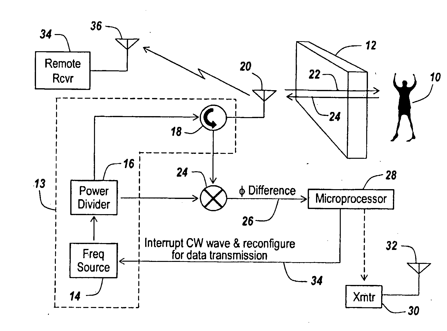
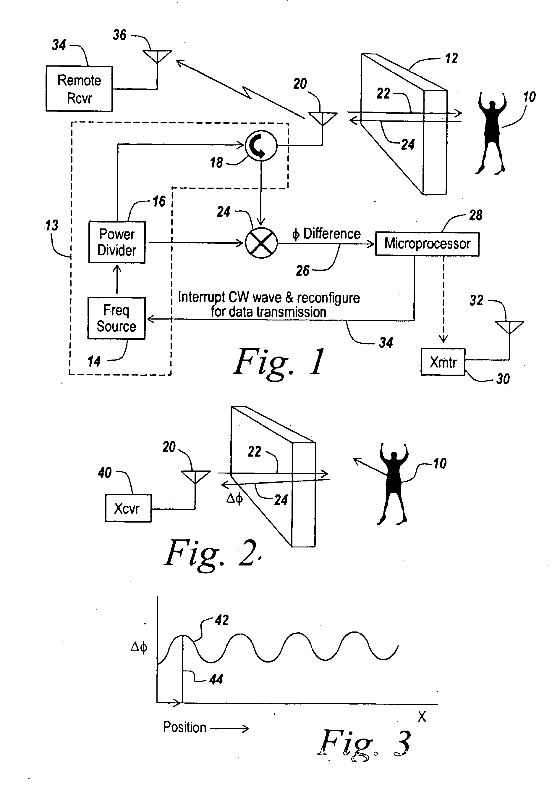
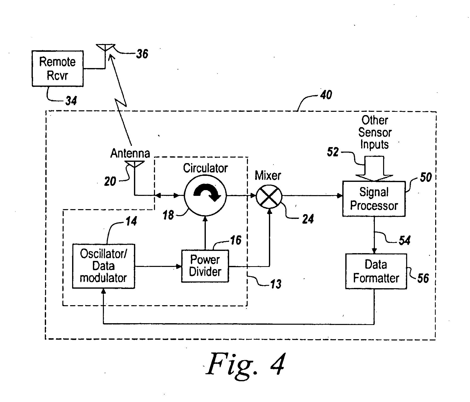
[0030]Referring now to FIG. 1, if it is important to detect the presence of an individual 10 behind a wall 12, then in one embodiment of the subject invention, a CW radar is used. This radar includes a transmitter 13 including a frequency source 14, a power divider 16 and a circulator 18 to drive a radar antenna 20.

[0031]The CW signal from antenna 20, here indicated by arrow 22, is projected through wall 12 towards individual 10, with returns 24 impinging on antenna 20. The return is then coupled via circulator 18 to a mixer 25.

[0032]The output of mixer 24 is indicated by arrow 26 to be the phase difference between the transmitted and returned signals. This signal is applied to a microprocessor 28 containing an analog-to-digital converter that functions in one aspect as a motion detector, the output of which indicates a moving object behind wall 12.

[0033]If one wished to remotely monitor of the motion detector output, one might provide a separate transmitter 30 and its own antenna 3...


PUM


Abstract

In a CW radar system for detecting motion behind a wall (12) involving modulation of the radar transmission, means (34) are provided to interrupt the CW wave when motion is detected and to use the same radar transmitter (30) to transmit a serial digital message to a remote monitoring receiver (34). The encoding can include a receiver wakeup message to turn on the receive only when motion has been detected. In one embodiment, a microprocessor (28) is used to detect when motion exists behind a wall and to provide a tailorable message to modulate the radar's transmitter in the period when the CW signal from the radar is turned off after the motion detector.

Description

RELATED APPLICATIONS[0001]This Application claims rights under 35 USC 119(e) from U.S. Application Ser. No. 60 / 538,011 filed Jan. 20, 2004, incorporated herein by reference.STATEMENT OF GOVERNMENT INTEREST[0002]The invention described herein was made under Contract No. N39998-97-C-5216 with the Government of the United States of America and may be manufactured and used by and for the Government of the United States of America for Governmental purposes without the payment of any royalties thereon or therefor.FIELD OF THE INVENTION[0003]This invention relates to small, relatively low-powered radar systems and more particularly to the provision of a remote display of radar results.BACKGROUND OF THE INVENTION[0004]As described in U.S. Pat. No. 6,633,254 issued to Eldon Sutphin, assigned to the assignee hereof and incorporated herein by reference, in the past, low-powered radar systems have been employed for use in intrusion alarms, vehicle sensing, surveillance and through-wall detectio...

Claims


Application Information

Patent Timeline
IPC IPC(8): G01S13/50G01S7/00G01S13/56G01S13/62
CPCG01S7/006G01S13/888G01S13/56
Inventor SUTPHIN, ELDON M.
Owner BAE SYST INFORMATION & ELECTRONICS SYST INTERGRATION INC
Why Eureka
Try Eureka