Backlight device and liquid crystal display apparatus

Active Publication Date: 2009-05-28
SATURN LICENSING LLC
View PDF8 Cites 35 Cited by
  • Summary
  • Abstract
  • Description
  • Claims
  • Application Information

AI Technical Summary

Benefits of technology

[0013]According to the embodiments of the invention, mounting a drive substrate on the other surface side of a reflector, which is on one surface side of the bottom chassis, that is, on the circumference of a light source substrate inside of the bottom chassis can decrease the nu

Problems solved by technology

It is difficult to further decrease the thickness of the backlight device since the inside of the bottom chassis has the light source substrates having LEDs and the outside has the drive substrates, tuner, protective member, radiating member and so on across the bottom chassis.
Therefore, it is difficult to decrease the thickness of the backlight

Method used


Image

  • Backlight device and liquid crystal display apparatus
  • Backlight device and liquid crystal display apparatus
  • Backlight device and liquid crystal display apparatus

Examples


Embodiment Construction

[0021]With reference to drawings, the backlight device and liquid crystal display apparatus to which the invention is applied will be described.

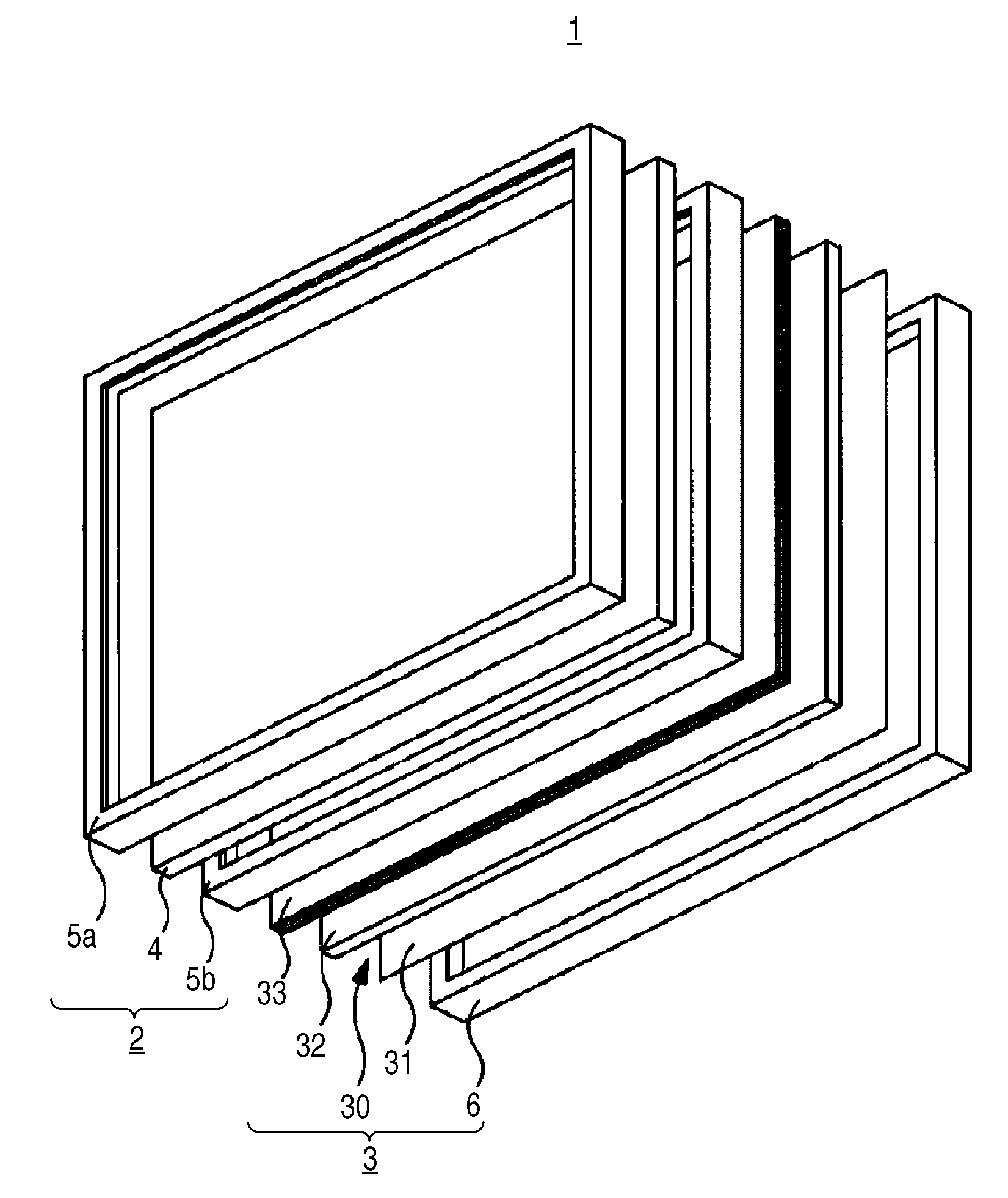
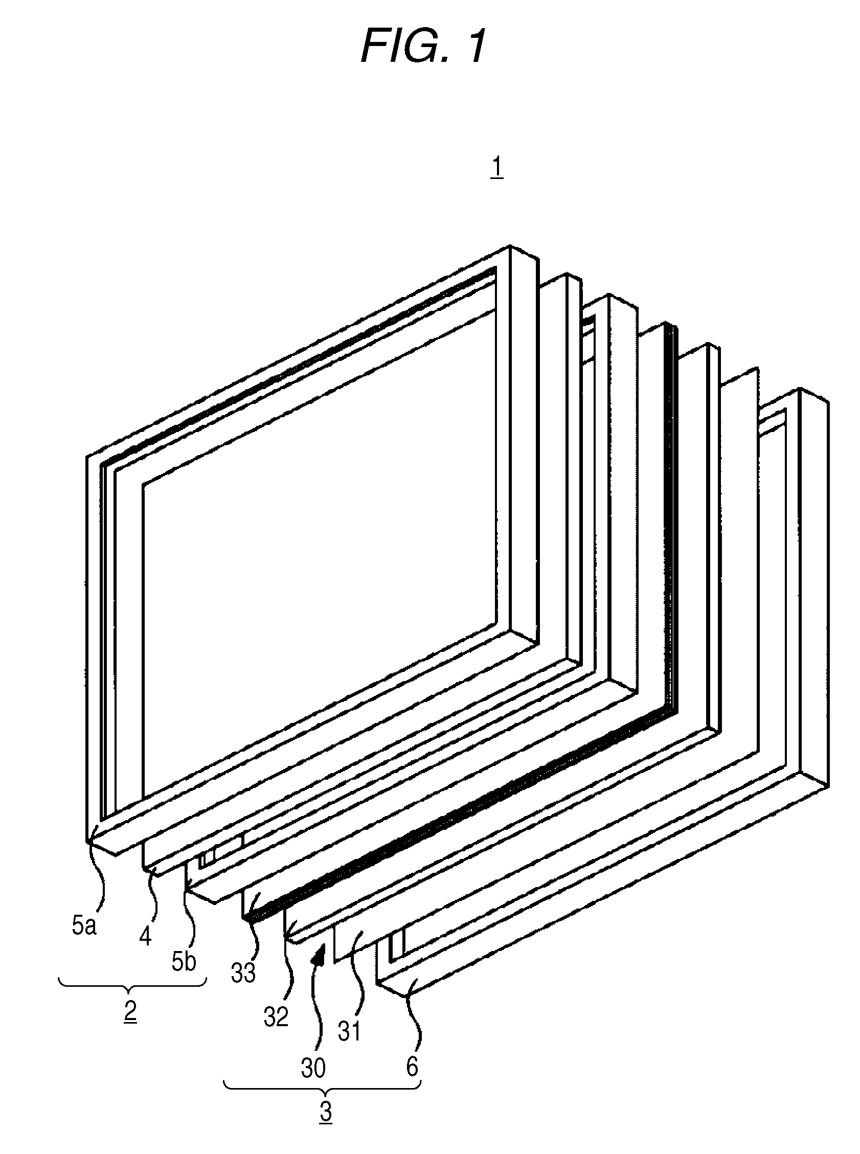
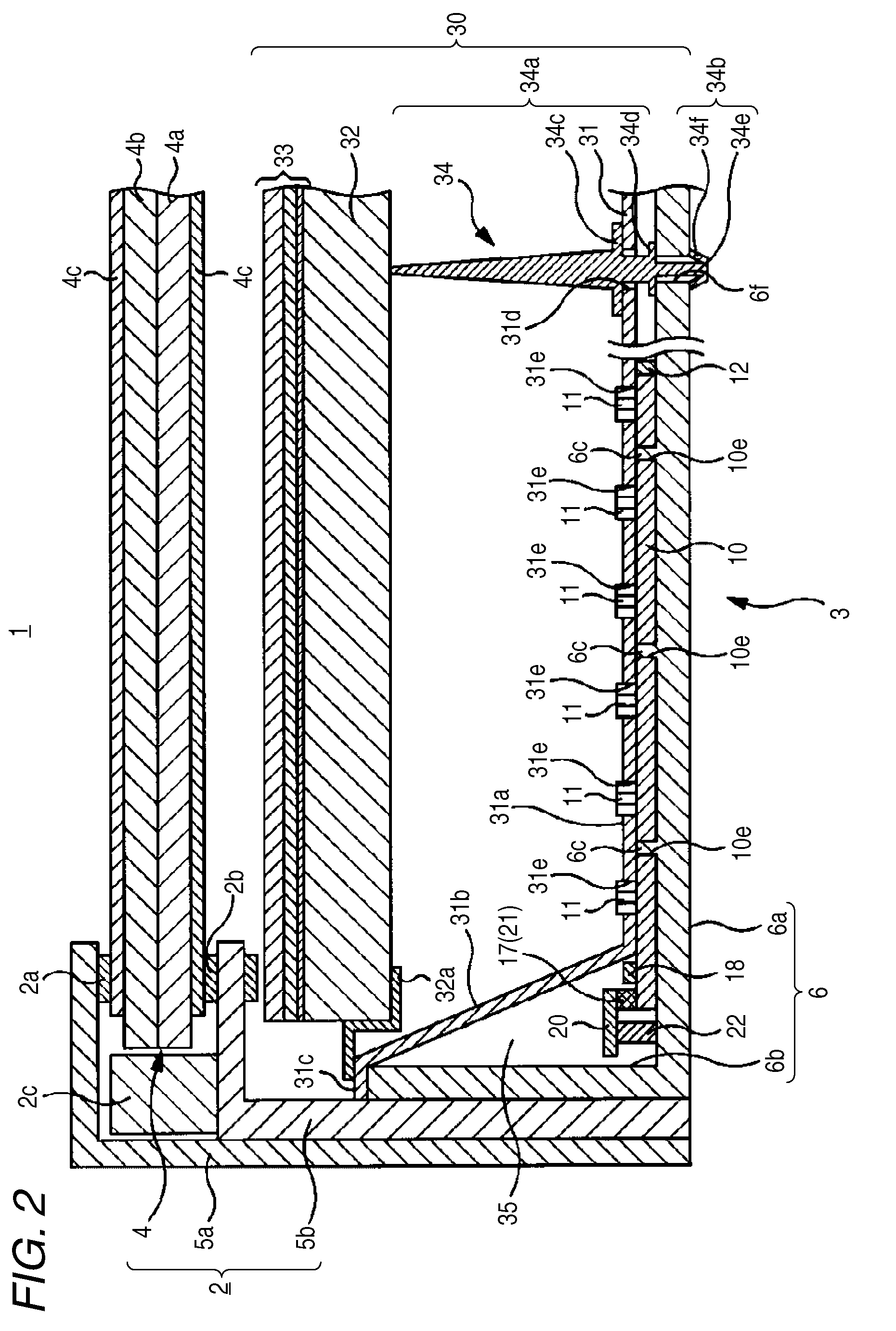
[0022]A liquid crystal display apparatus 1 to which the invention is applied may be used as a display panel for a television receiver having a large display screen. The liquid crystal display apparatus 1 includes, as shown in FIGS. 1 and 2, a liquid crystal panel unit 2 having a transmissive liquid crystal panel 4, and a backlight unit 3 to which the invention is applied. The backlight unit 3 is combined with the liquid crystal panel unit 2 on the back side thereof and irradiates illumination light to the liquid crystal panel unit 2.

[0023]The liquid crystal panel unit 2 to which the backlight unit 3 irradiates illumination light from the back side has a substantially rectangular liquid crystal panel 4 and a front frame member 5a and back frame member 5b, both of which hold the liquid crystal panel 4.

[0024]The liquid crystal panel 4 held by t...


PUM


Abstract

A backlight device that illuminates a transmissive liquid crystal panel is disclosed. The device includes: a plurality of light source substrates on which a plurality of light emitting devices irradiating illumination light are mounted; drive substrates having drive circuits for the light emitting devices and electrically connected to the light source substrates; a bottom chassis having one surface to which the plurality of light source substrates are attached; a reflector having openings corresponding to the light emitting devices and through which the light emitting devices are exposed, and reflecting the illumination light; a diffuser facing the one surface side of the reflector through a predetermined facing interval and internally diffusing the illumination light; and an optical function sheet laminate combined with the diffuser on one surface side thereof, containing a stack of a plurality of optical function sheets and guiding the illumination light to the liquid crystal panel.

Description

CROSS REFERENCES TO RELATED APPLICATIONS[0001]The present invention contains subject matter related to Japanese Patent Application JP 2007-303607 filed in the Japanese Patent Office on Nov. 22, 2007, the entire contents of which being incorporated herein by reference.BACKGROUND OF THE INVENTION[0002]1. Field of the Invention[0003]The present invention relates to a backlight device that illuminates a transmissive liquid crystal panel and a liquid crystal display apparatus including the backlight device.[0004]2. Description of the Related Art[0005]A liquid crystal display apparatus has liquid crystal filled between two transparent substrates. The application of voltage thereto changes the direction of liquid crystal molecules and thus changes the optical transmittance, whereby the liquid crystal display apparatus can optically display a predetermined picture. Since liquid crystal itself is not a light emitter, some liquid crystal display apparatus may include a backlight device that i...

Claims


Application Information

Patent Timeline
IPC IPC(8): G02F1/13357G02F1/1333
CPCG02F1/133603G02F2001/133613G02F1/133608G02F1/133606G02F1/133613
Inventor KAWASE, MITSUHIROSHIRAKUMA, TOSHIAKI
Owner SATURN LICENSING LLC
Why Eureka
Try Eureka