Digital micromirror device module

Inactive Publication Date: 2009-05-28
CORETRONIC
View PDF7 Cites 23 Cited by
  • Summary
  • Abstract
  • Description
  • Claims
  • Application Information

AI Technical Summary

Benefits of technology

[0007]The present invention relates to a DMD mod

Problems solved by technology

Conventional DMD modules are complicated designed with many elements, for example, compression springs are telescoped on the multi section screws.
The compression springs and multi section screws increase costs.
Furthermore, the compression quantity of each compression spring differs from one another, thus, thermal load distr

Method used


Image

  • Digital micromirror device module
  • Digital micromirror device module
  • Digital micromirror device module

Examples


Example

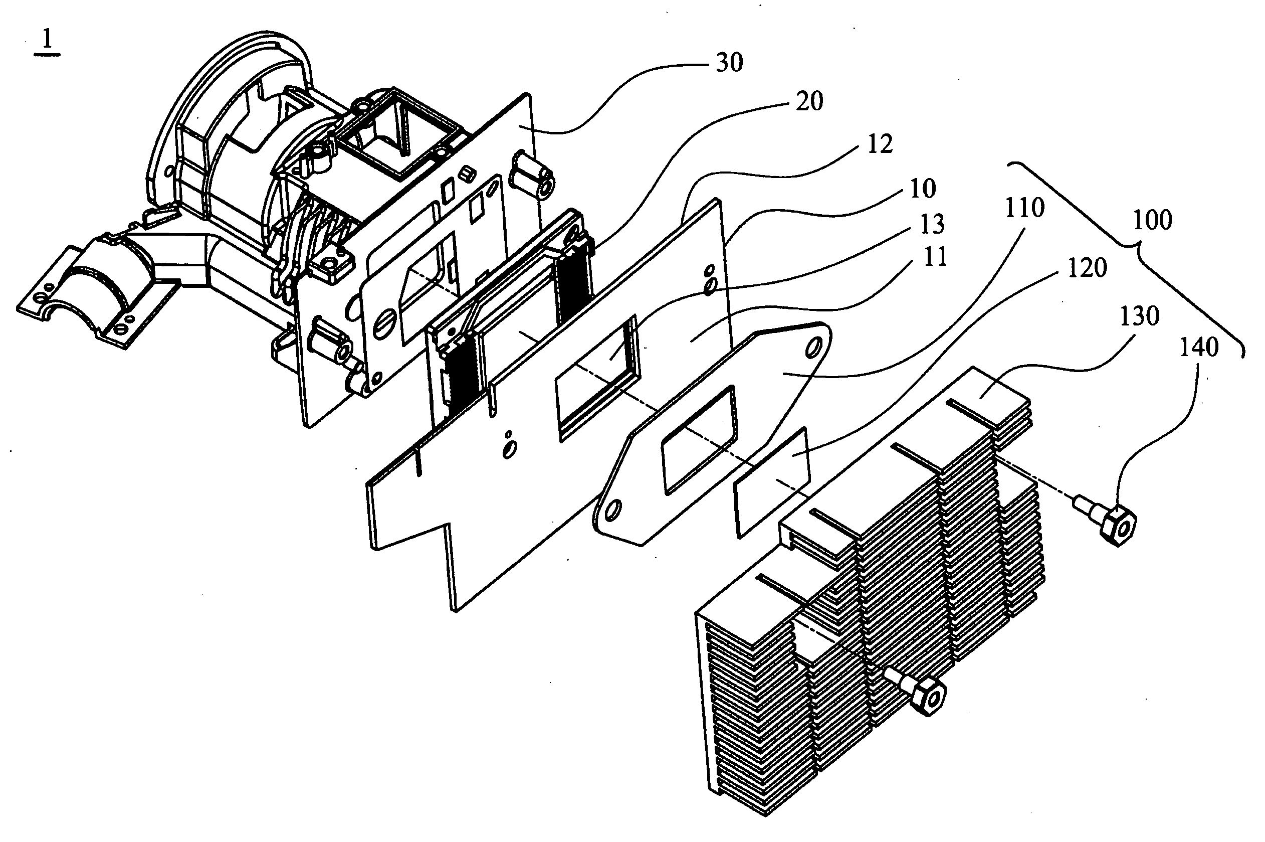
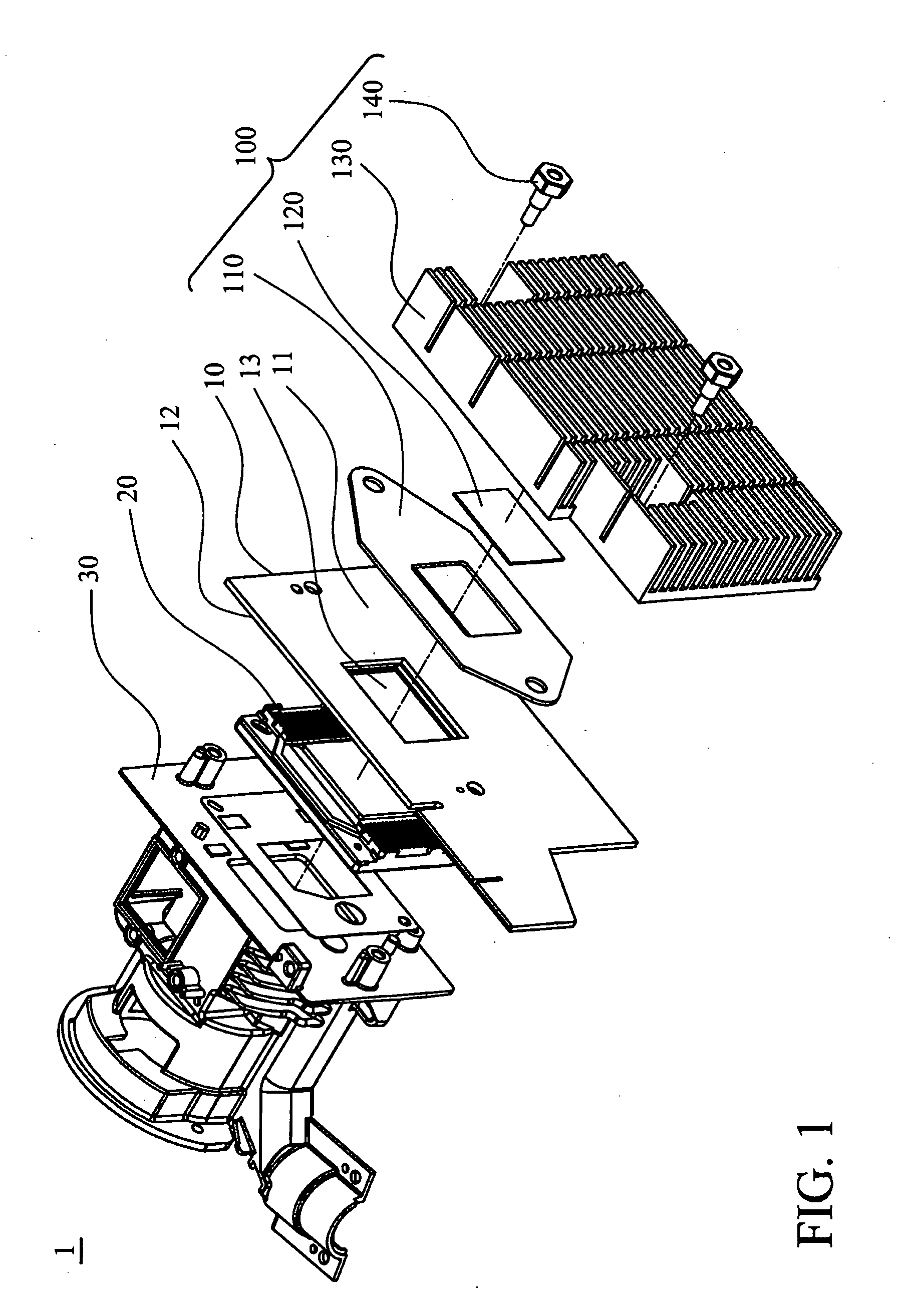
[0019]FIG. 1 shows a DMD (Digital Micromirror Device) module 1 of a first embodiment of the invention including a circuit board 10, a DMD element 20, a socket (not shown), a housing 30 and a heat conducting unit 100. The heat conducting unit 100 includes a soft elastic pad 110, a heat dissipation pad 120, a heat sink 130 and a plurality of fixers 140.

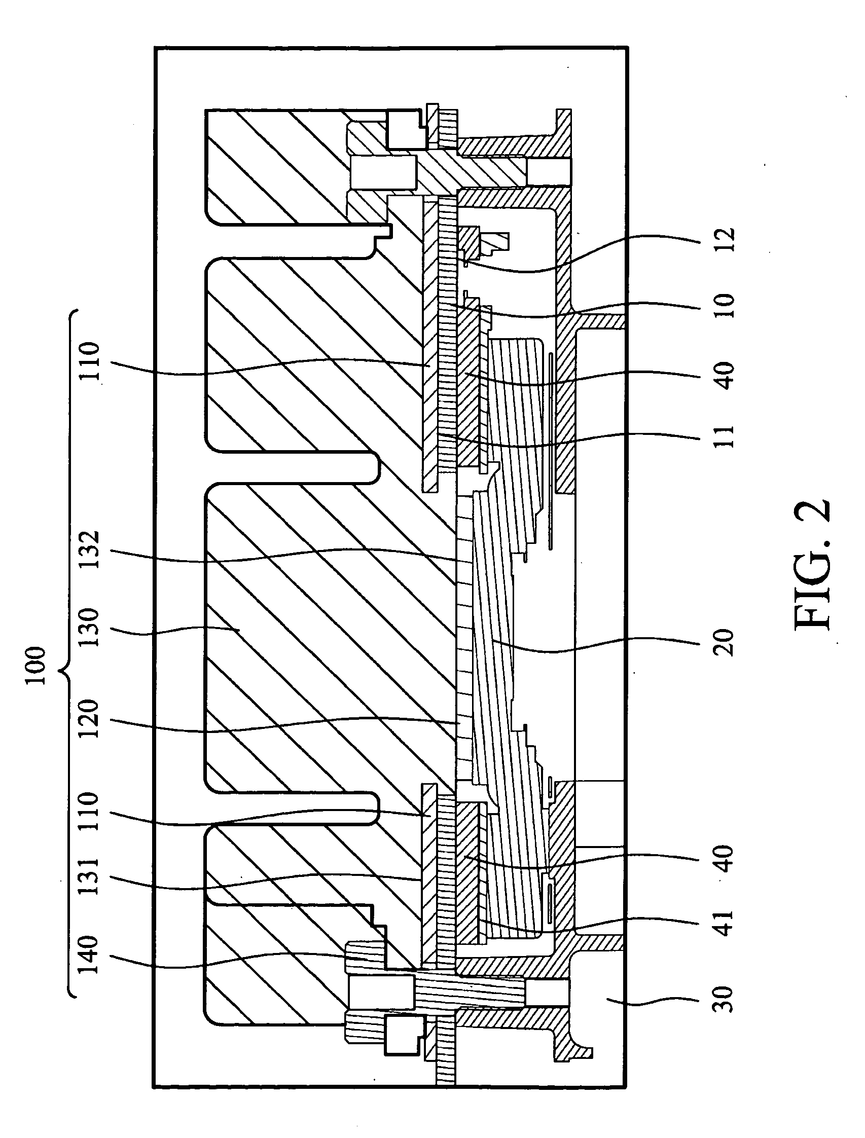
[0020]The circuit board 10 includes a first surface 11, a second surface 12 and a through hole 13. The first surface 11 is opposite to the second surface 12. The socket (not shown) is welded on the second surface 12 of the circuit board 10. The DMD element 20 is electrically connected to the circuit board 10 via the socket. The soft elastic pad 110 is disposed on the first surface 11 and surrounds the through hole 13, so as to make the heat dissipation pad 120 pass through the through hole 13 and contact the DMD element 20. The soft elastic pad 110 is sandwiched between the heat sink 130 and the circuit board 10. The heat dissipation pa...

Example

[0023]FIG. 3 shows a DMD module 1′ of a second embodiment of the invention. Similar to the first embodiment, the DMD module 1′ includes a circuit board 10, a DMD element 20, a socket 40′, a housing 30 and a heat conducting unit 100. The heat conducting unit 100 includes a soft elastic pad 110, a heat dissipation pad 120, a heat sink 130 and a plurality of fixers 140. The second embodiment differs from the first embodiment in that the socket 40′ is electrically connected to the DMD element 20 and the circuit board 10 via elastic pins.

[0024]The foregoing descriptions of the preferred embodiments of the present invention have been presented for purposes of illustration and description. It is not intended to be exhaustive or to limit the present invention to a precise form or to the exemplary embodiments disclosed. Accordingly, the foregoing description should be regarded as illustrative rather than restrictive. Obviously, a variety of modifications and variations will be apparent to th...


PUM


Abstract

A digital micromirror device (DMD) module includes a circuit board, a DMD element, a soft elastic pad, a heat dissipation pad and a heat sink. The circuit board includes a first surface, a second surface and a through hole, wherein the first surface is opposite to the second surface. The DMD element is electrically connected to the circuit board. The soft elastic pad is disposed on the first surface of the circuit board and surrounds the through hole. The heat dissipation pad passes through the through hole and contacts the DMD element. The soft elastic pad is sandwiched between the circuit board and the heat sink, the heat dissipation pad is sandwiched between the heat sink and the DMD element, and the heat sink contacts the soft elastic pad and the heat dissipation pad, so as to apply a force to the soft elastic pad and the heat dissipation pad.

Description

CROSS REFERENCE TO RELATED APPLICATIONS[0001]This application claims priority of Taiwan Patent Application No. 096144933, filed on Nov. 27, 2007, the entirety of which is incorporated by reference herein.BACKGROUND OF THE INVENTION[0002]1. Field of the Invention[0003]The present invention relates to a Digital Micromirror Device (DMD) module, and more particularly to a DMD module with a simplified structure.[0004]2. Description of the Related Art[0005]In a Digital Micromirror Device (DMD) module, an electrical load controlling the electrical connection states and a thermal load controlling the heat connection states are adjusted according to the designing style of the DMD element, so as to improve electrical conduction and heat dissipation effect. Conventional DMD modules, for example, a DMD module made by Texas Instruments, utilizes shoulder screws and push nuts to control electrical load and thermal load, separately. Additionally, compression springs and flat springs are utilized i...

Claims


Application Information

Patent Timeline
IPC IPC(8): H05K7/20
CPCH05K7/20472G02B26/0833
Inventor CHEN, JUNG-CHICHEN, CHE-HSUEH
Owner CORETRONIC
Why Eureka
Try Eureka