
Spindle device for machine tool

Inactive Publication Date: 2009-05-28
DMG MORI SEIKI CO LTD +1
View PDF5 Cites 9 Cited by
  • Summary
  • Abstract
  • Description
  • Claims
  • Application Information

AI Technical Summary

Benefits of technology

[0018]Further, in the present invention, the second rotor of the second drive motor is so disposed that the drive mechanism of the clamping means is contained inside the second rotor. Thus, the second drive motor can be disposed while effectively utilizing a space for disposing the drive mechanism, which has been conventionally needed. This eliminates a need of elongating the spindle device in an axial direction of the spindle, and thus, the second drive motor can be arranged in the spindle device. Therefore, even when the second drive motor is arranged, the spindle device may be made as compact as conventional configurations in size.
[0021]Therefore, in this case also, it is possible to switch between when the spindle is driven by the first drive motor and when the spindle is driven by at least the second drive motor, and thus, an effect similar to that described above can be obtained. Further, the second rotor is disposed outside the cylinder and the third member, and thus, the clamping means and the connecting means can be more efficiently disposed. As a result, a more compact device configuration can be embodied.
[0023]As described above, according to the spindle device for a machine tool according to the present invention, the spindle device for a machine tool is compatible with both high-speed cutting and low-speed cutting while maintaining the spindle device for a machine tool compact in size.

Problems solved by technology

On the other hand, depending on a quality of material for a workpiece, which is an object to be machined, the high-speed cutting is not possible, and thus, there may be a need of rotating the spindle at a low speed to carry out the machining.
However, a spindle device corresponding to the high-speed cutting has small output at the time of the low-speed rotation, and thus, low-speed cutting cannot be carried out.
As a result, there is a limit to a single machine tool carrying out all types of machining works.
Therefore, it is not possible to directly apply the spindle device disclosed in the Patent Document 1 so configured that the spindle, the first rotation axis, the clutch mechanism, and the second rotation axis are disposed in a straight line in the axial direction of the spindle, to the spindle device in which the above-described clamping device is arranged.
Further, when the spindle, the first rotation axis, the clutch mechanism, and the second rotation axis are merely disposed in the axial direction of the spindle, a length in the spindle axial direction in the spindle device is elongated, thereby resulting in a problem in that a device configuration becomes large.

Method used


Image

  • Spindle device for machine tool
  • Spindle device for machine tool
  • Spindle device for machine tool

Examples


Embodiment Construction

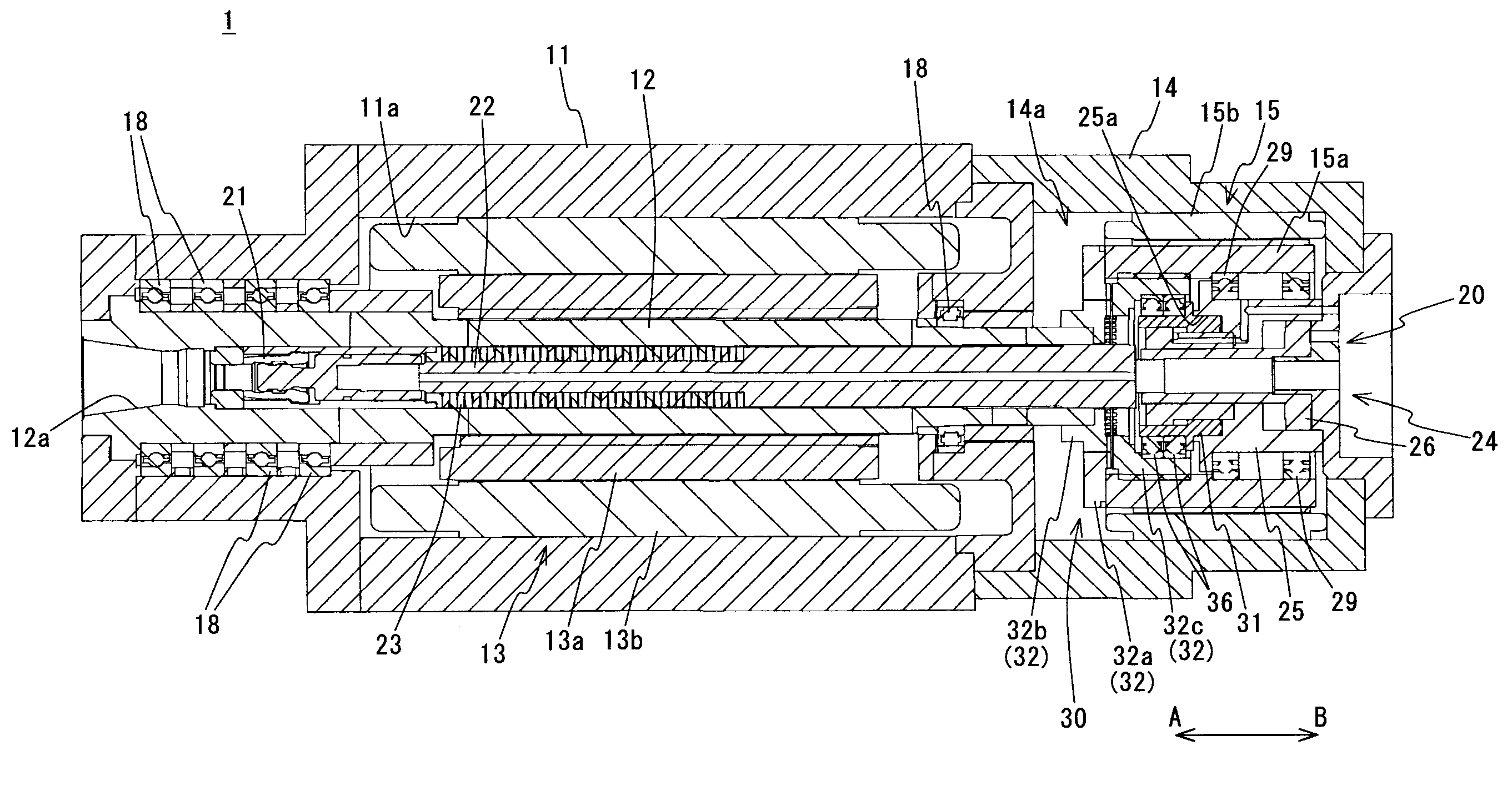
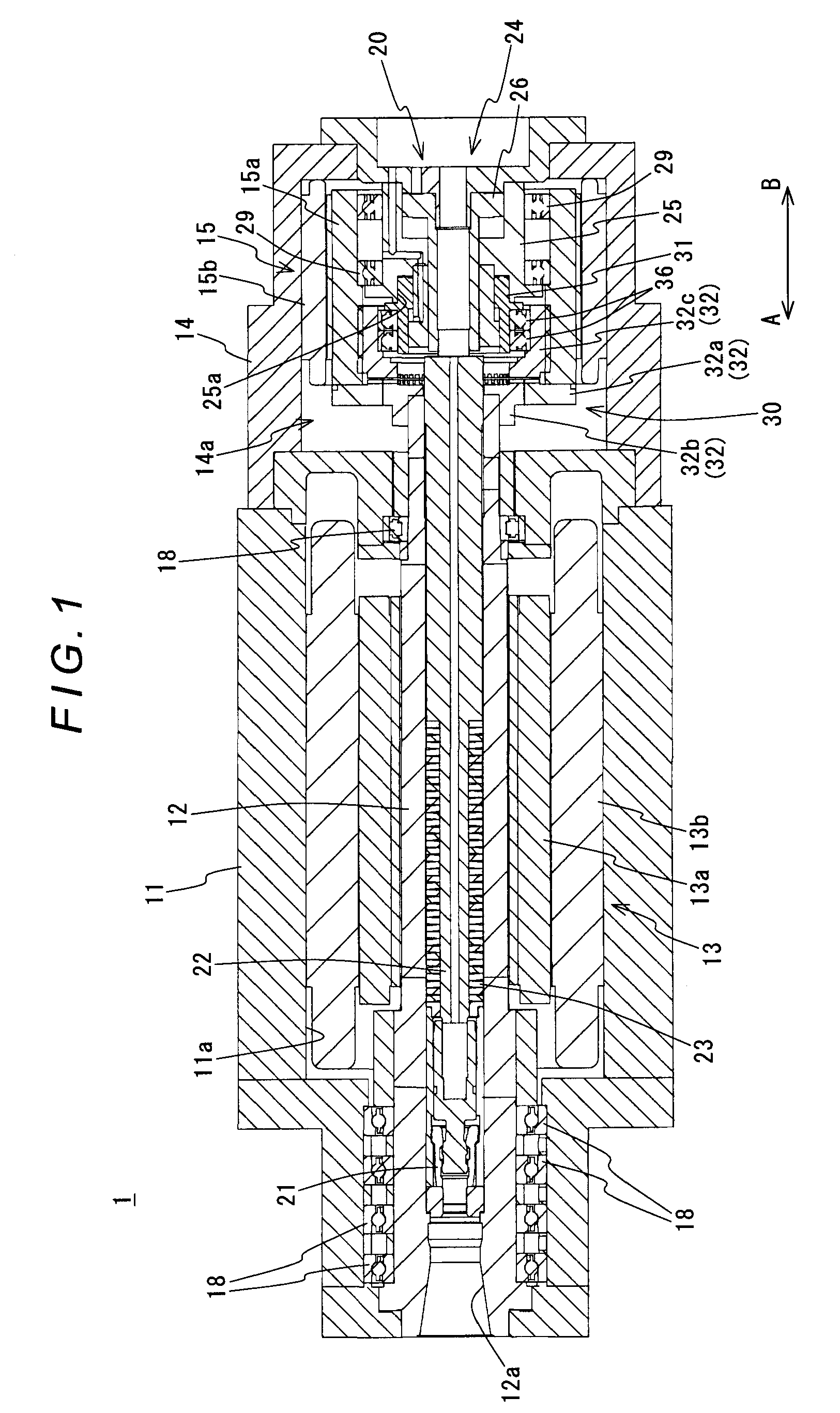
[0028]A specific embodiment of the present invention is described as follows based on the appended drawings. FIG. 1 and FIG. 2 are sectional views showing a schematic configuration of a spindle device for a machine tool according to one embodiment of the present invention. FIG. 3 and FIG. 4 are detailed views of an interior of a rear housing.

[0029]As shown in FIG. 1 and FIG. 3, a spindle device 1 for a machine tool of the present embodiment is provided with: a front housing 11; a spindle 12 rotatably supported about an axis within the front housing 11 and having a tip end thereof being attached with a tool; a first drive motor 13 disposed within the front housing 11; a rear housing 14 installed on a rear end side of the spindle 12 in the front housing 11; a second drive motor 15 disposed within the rear housing 14; a clamping mechanism 20 for clamping / unclamping the tool attached to the tip end of the spindle 12; a connecting mechanism 30 for carrying out a connecting operation so a...


PUM

PropertyMeasurementUnit
Timeaaaaaaaaaa
Distanceaaaaaaaaaa

Abstract

A machine-tool spindle device includes: a spindle; a front housing for rotatably supporting the spindle; a first drive motor having a first rotor installed securely on the spindle and a first stator installed securely within the front housing; a rear housing installed on a rear end side of the spindle in the front housing; a second drive motor having an annular second rotor which is disposed coaxially to the spindle near a rear end of the spindle and which is supported rotatably within the rear housing, and a second stator installed securely within the rear housing; a connecting mechanism for connecting the rear end of the spindle and the second rotor and releasing the connection; and a clamping mechanism, disposed within the attaching hole of the spindle and within the second rotor, for clamping a tool attached to the spindle.

Description

BACKGROUND OF THE INVENTION[0001]1. Technical Field[0002]The present invention relates to a spindle device for a machine tool, provided with: a spindle which is arranged rotatably about an axis and to which a tool is attached; and a drive motor for rotating the spindle about the axis.[0003]2. Description of the Related Art[0004]In a spindle device for a machine tool, such as a machining center, progress has been conventionally made in achieving a higher speed of a spindle rotation. The reason for this is to implement a higher speed machining to shorten a machining time, thereby achieving effective machining. On the other hand, depending on a quality of material for a workpiece, which is an object to be machined, the high-speed cutting is not possible, and thus, there may be a need of rotating the spindle at a low speed to carry out the machining. However, a spindle device corresponding to the high-speed cutting has small output at the time of the low-speed rotation, and thus, low-sp...

Claims


Application Information

Patent Timeline
IPC IPC(8): B23C7/00
CPCB23Q5/10B23Q2005/005Y10T408/50Y10T409/303976Y10T409/304088Y10T409/309464
Inventor SOSHI, MASAKAZUISHIGURO, HARUKIMOCHIZUKI, AKIHIRO
Owner DMG MORI SEIKI CO LTD
Features
  • Generate Ideas
  • Intellectual Property
  • Life Sciences
  • Materials
  • Tech Scout
  • Unparalleled Data Quality
  • Higher Quality Content
  • 60% Fewer Hallucinations
Learn More