

Centrifugally Projecting Machine
a centrifugal projecting machine and projector technology, which is applied in the direction of rotor blades, grinding/polishing apparatus, manufacturing tools, etc., can solve the problems of reducing the life of rotating parts, and affecting the operation of centrifugally projecting machines. the effect of maintenan
- Summary
- Abstract
- Description
- Claims
- Application Information
AI Technical Summary
Benefits of technology
Problems solved by technology
Method used
Image

Examples
first embodiment
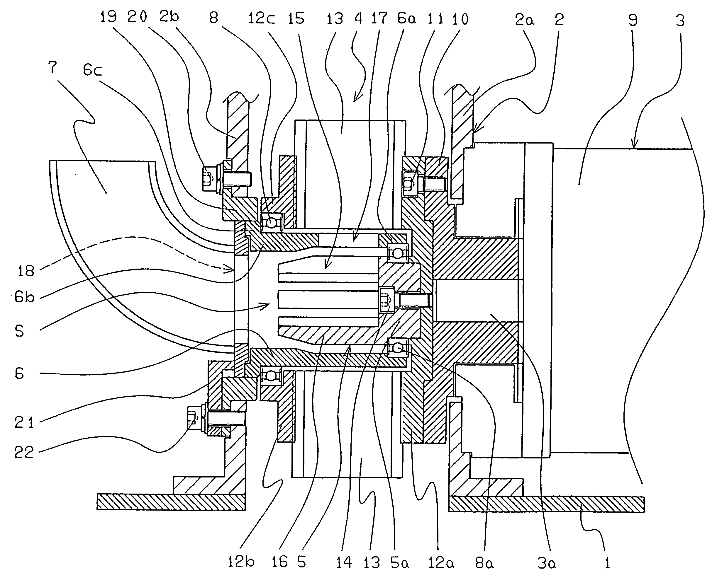
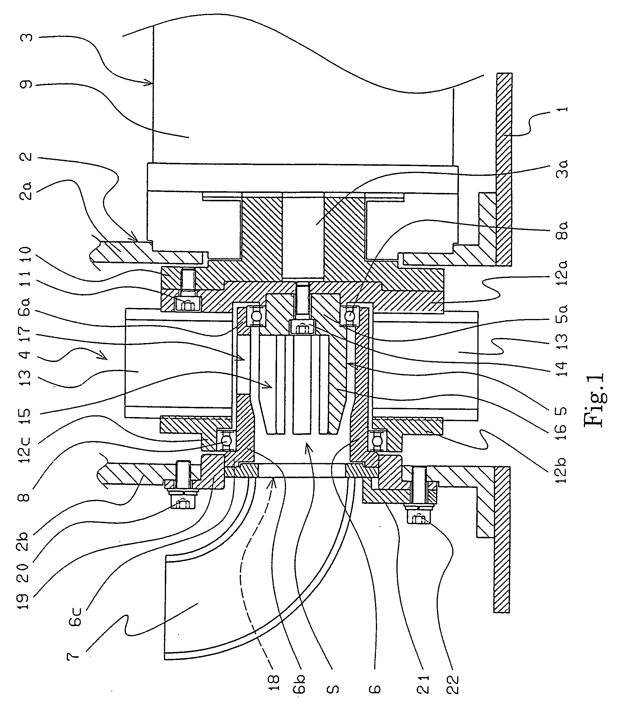
[0038]Below, the centrifugally projecting machine of this invention is explained based on the figures. As shown in FIG. 1, the centrifugally projecting machine of this invention comprises:
[0039]a housing 2 (a casing for the impeller) disposed on a top surface 1 of a box for projecting shot from a main body of the machine,
[0040]a driving means 3 disposed on the top surface 1 and at the outer first side 2a of the housing 2,
[0041]an impeller 4 connected to a driving shaft 3a of the driving means 3,
[0042]a distributor 5 disposed in the inner cylindrical space S of the impeller 4 so that it is concentrically arranged in relation to the driving shaft 3a,
[0043]a control cage 6 connected to a second side 2b of the housing 2, opposite its first side 2a,
[0044]a nozzle 7 connected to the second side 2b of the housing 2, and
[0045]a supporting member 8 disposed between the second side-plate of the impeller 4 and the proximal end 6b of the control cage 6.
[0046]The means for supporting the impel...
second embodiment
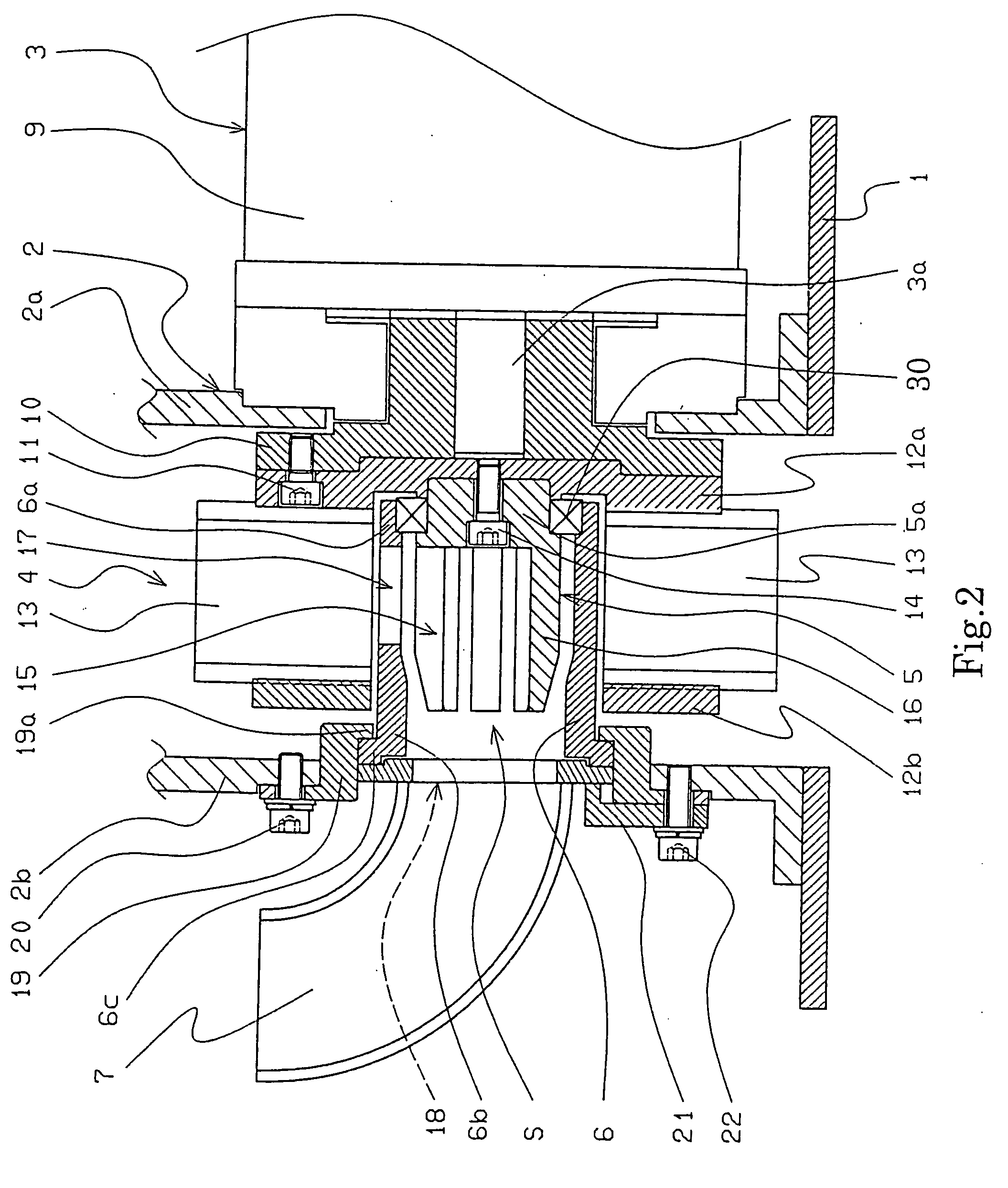
[0063]For the centrifugally projecting machine of this invention, the distributor 5 is supplied with the shot from the nozzle 7 through the control cage 6. The shot are stirred in the rotating distributor 5.
[0064]The shot that are stirred in the control cage 6 are supplied to the inner portion of the rotating blades 13 through the opening 17 for dispersing the shot, of the control cage 6. Then, the rotating member 30 for sealing prevents the shot from being projected at the inner surface of the housing 2. The speed of the shot that are supplied to the blades 13 is gradually accelerated by the rotating blades 13. The shot are ejected from the periphery of the blades 13 and are projected at a product that is to be processed to remove rust, burrs, scales, or a composition for coating the surface of the product.
third embodiment
[0065]FIG. 3 shows a centrifugally projecting machine of this invention.
[0066]The centrifugally projecting machine of the third embodiment comprises:
[0067]a housing 52 (a casing for an impeller) disposed on a top surface 51 of a box for projecting shot from a main body of the machine,
[0068]a driving motor 54 (a driving means) disposed at the first side 52a (a cover) of the housing 52 by means of a flange 53,
[0069]an impeller 57 connected to a driving shaft 54a of the driving motor 54 by means of a hub 56 that is connected to the driving shaft 54a by a tapered locking device comprising a tapered sleeve 55a and a tapered locking nut 55b,
[0070]a distributor 58 disposed in the inner cylindrical space S of the impeller 57 so that it is concentrically arranged in relation to the driving shaft 54a,
[0071]a control cage 59 connected to a second side 52b of the housing 52, opposite its first side 52a, and
[0072]a nozzle 60 connected to the second side 52b of the housing 52,
[0073]wherein a be...
PUM
| Property | Measurement | Unit |
|---|---|---|
| diameter | aaaaa | aaaaa |
| length | aaaaa | aaaaa |
| outer diameter | aaaaa | aaaaa |
Abstract
Description
Claims
Application Information