Self-advancing device

a self-advancing device and technology of a self-advancing device, applied in the field of medical instruments, can solve the problems of affecting the construction of the endoscope, the discomfort of the patient, and the relatively complex structure of the mechanism to achieve the motion, and achieve the effect of reducing the impa

Inactive Publication Date: 2009-05-28
ENDOGEN
View PDF9 Cites 56 Cited by
  • Summary
  • Abstract
  • Description
  • Claims
  • Application Information

AI Technical Summary

Benefits of technology

[0010]In some embodiments, the element is driven under action of a fluid and the device includes control means to allow fluid flow between the element and the body to be controlled so as to effect deceleration and acceleration of the element toward and away from the end of the body.
[0011]The device may define a first flow path for applying pressurized fluid to a rear of the element and a second flow path for allowing the fluid to be discharged from between a front of the element and the end...

Problems solved by technology

In that manner, the endoscopes rely on external pushing as their source of forward motion and the resultant construction of the mechanisms to achieve that motion can be relatively complex.
A disadvantage of such an arrangement is that the impact of the...

Method used


Image

  • Self-advancing device
  • Self-advancing device
  • Self-advancing device

Examples


Embodiment Construction

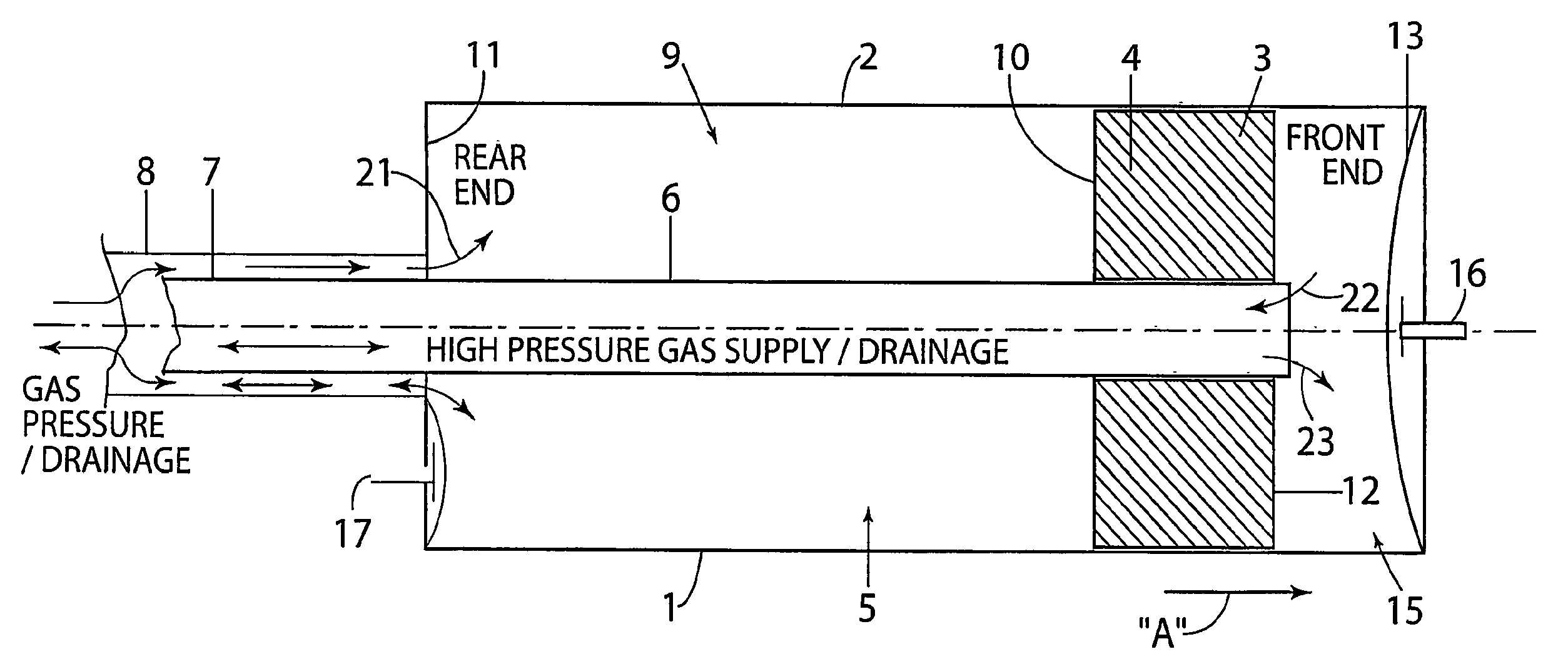
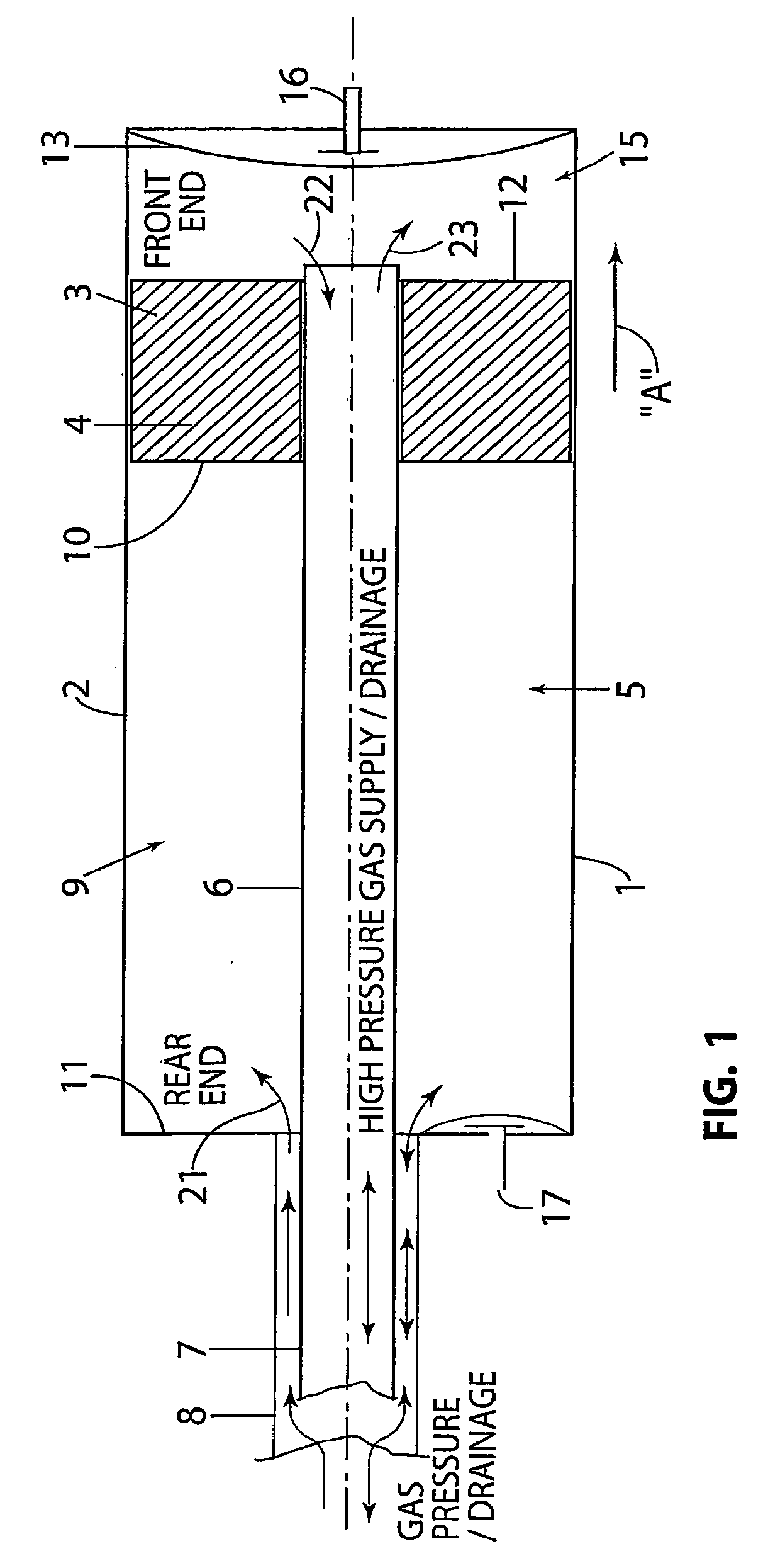
[0027]A self-advancing device 1 is shown in FIG. 1 as including an elongate body 2 with a movable mass 3, in the form of piston element 4 arranged for sliding movement along a channel 5 formed within a body 2. The body 2 is mounted on an axially extending conduit 6, which projects into the body 2 from a pipe 7. A second coaxial pipe 8 is also provided for fluid communication with a first region 9 of the channel 5, between a rear end 10 of the element 4 and a rear end 11 of the body 2. The pipe 7 maintains fluid communication with a second region 15, between a front end 12 of the element 4 and a front end 13 of the tube. Sensors 16 and 17 are also provided to detect proximity of the element relative to either end 11 or 13 of the body 2. The sensors 16,17 are shown for illustrative purposes only and they need not be in the locations shown. Indeed, the sensors may be dispensed with entirely provided the position of the element 4 within the body 2 is known or can at least be appropriate...


PUM


Abstract

A device which includes an elongate body with a movable mass arranged for sliding movement within the body is disclosed. The element is arranged to decelerate toward an end of the body in order to impart forward movement thereto, via momentum transfer, and is further arranged to accelerate away from said end in order to further drive the body forward, again using momentum transfer.

Description

CROSS-REFERENCE TO RELATED APPLICATIONS[0001]This application is a continuation of U.S. application Ser. No. 10 / 499,426 filed Sep. 13, 2004 (issued on Jan. 27, 2009 as U.S. Pat. No. 7,481,764), which is a National Stage application of PCT Application No. PCT / AU02 / 01733, filed on Dec. 20, 2002, which claims priority to Australian Patent Application Nos. PS 1610 / 02 (filed on Apr. 8, 2002), PS 0647 / 02 (filed on Feb. 21, 2002), and PR 9678 / 01 (filed on Dec. 20, 2001). Each of the above-referenced applications is incorporated by reference in its entirety.BACKGROUND[0002]1. Field[0003]The invention relates to a self-advancing device particularly, but not exclusively, for use in the field of medical instrumentation.[0004]2. Description of the Related Art[0005]A number of self-advancing mechanisms are used in the medical industry to advance instruments, such as an endoscope, internally of a patient's body.[0006]Self-advancing endoscopes are disclosed in, for example, U.S. Pat. No. 4,934,786...

Claims


Application Information

Patent Timeline
IPC IPC(8): A61B1/005A61B1/01B23Q5/00A61B1/00G02B23/24A61B1/015A61M25/01
CPCA61B1/00156A61M25/0122A61B1/015A61B1/00
Inventor SOUTORINE, MIKHAILGULIA, NURBEYTCHEPIKOV, IGOR
Owner ENDOGEN
Why Eureka
Try Eureka