Vertebral implants adapted for posterior insertion

a technology of vertebral implants and posterior insertion, which is applied in the field of endoprosthetic implants to replace intervertebral discs, can solve the problems of increasing pressure, limiting spinal movement, and wear and damage of fibrocartilage in intervertebral discs, and achieves the elimination of most posterior spinal pathology, prolonging wear life, and reducing the effect of fibrocartilag

Inactive Publication Date: 2009-05-28
SIMONSON CYNTHIA JEANNE
View PDF4 Cites 3 Cited by
  • Summary
  • Abstract
  • Description
  • Claims
  • Application Information

AI Technical Summary

Benefits of technology

[0018]It is also an object of this invention to provide an intervertebral endoprosthesis which utilizes a mechanical spring to achieve a longer wear life and accommodate increased intervertebral forces.
[0019]Still another object of this invention is to provide an endoprosthesis which substantially eliminates most posterior spinal pathology.
[0020]Yet another object of this invention is to provide an endoprosthesis which eliminates the need for facet joints.

Problems solved by technology

For example, the fibrocartilage in the intervertebral discs often becomes worn or damaged through wear, age and / or disease.
This damage limits spinal movements and can also result in pain as nerves become pinched and swollen.
Damaged fibrocartilage, in turn, increases the pressure that is otherwise encountered by the facet joint adjacent the disc.
This causes a premature wearing of the bone that makes up the joint.
Again, limited spinal movement and pain result.
Such methods, however, have serious drawbacks in that the resulting fused vertebrae limit the overall movement of the spine.
Furthermore, once two vertebrae are fused, the pressures encountered by adjacent healthy discs is increased.
This dramatically increases the likelihood that such healthy discs may become damaged and worn.
Nonetheless, the elastomerics typically wear out over the life of the prosthetic.
As a result, additional medical procedures are required to replace the worn out prosthetic.
Even prior to wearing out, elastomerics may simply wear unevenly, whereby the prosthetic provides an uneven resilient force between the vertebrae.
This causes nerves to become pinched and swollen.
Absent any type of wearing, elastomerics do not provide a cushioning effect that is equivalent to naturally occurring fibrocartilage.
This results in premature wearing of the joint.
Although each of the above-referenced inventions achieves its individual objective, they all suffer from common problems.

Method used


Image

  • Vertebral implants adapted for posterior insertion
  • Vertebral implants adapted for posterior insertion
  • Vertebral implants adapted for posterior insertion

Examples


Embodiment Construction

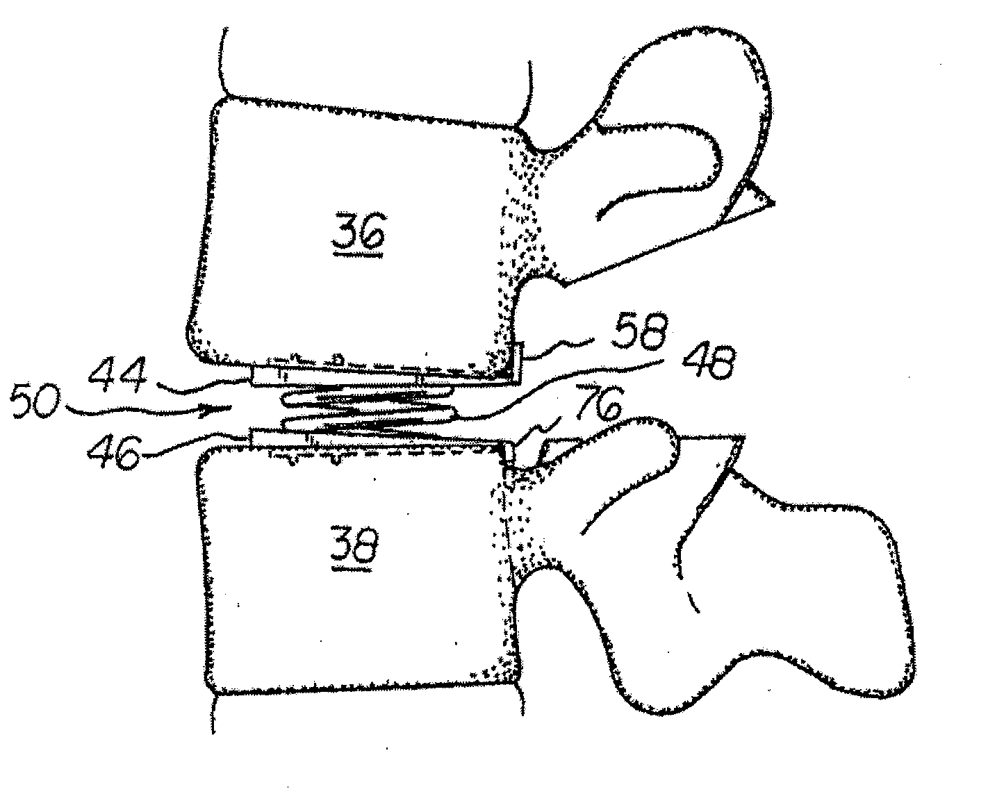
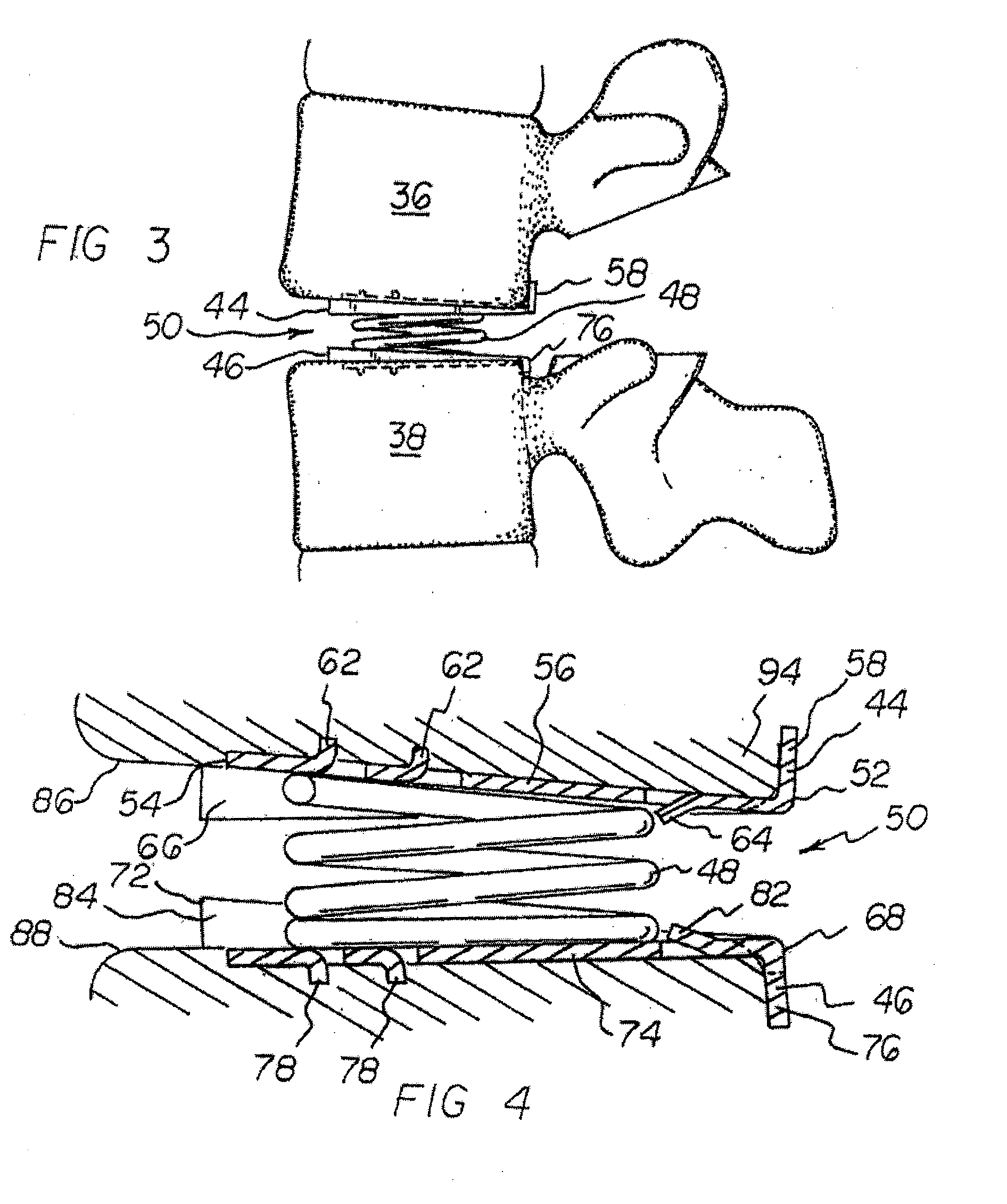
[0066]The present invention relates to an endoprosthetic implant for a human spinal disc. The structure of the implant allows it to be inserted posteriorly. This insertion is accomplished by performing a partial discectomy in the affected region. An intervertebral space is then created by removing the fibrocartilage between the facing surfaces of adjacent vertebrae. The implant is then inserted into the intervertebral space. The implant is thus adapted to replace damaged or worn intervertebral discs. Furthermore, the structure of the implant, and its posterior insertion, alleviate most spinal pathologies. The implant of the present invention, and the manner in which it is employed, are described in fuller detail hereinafter.

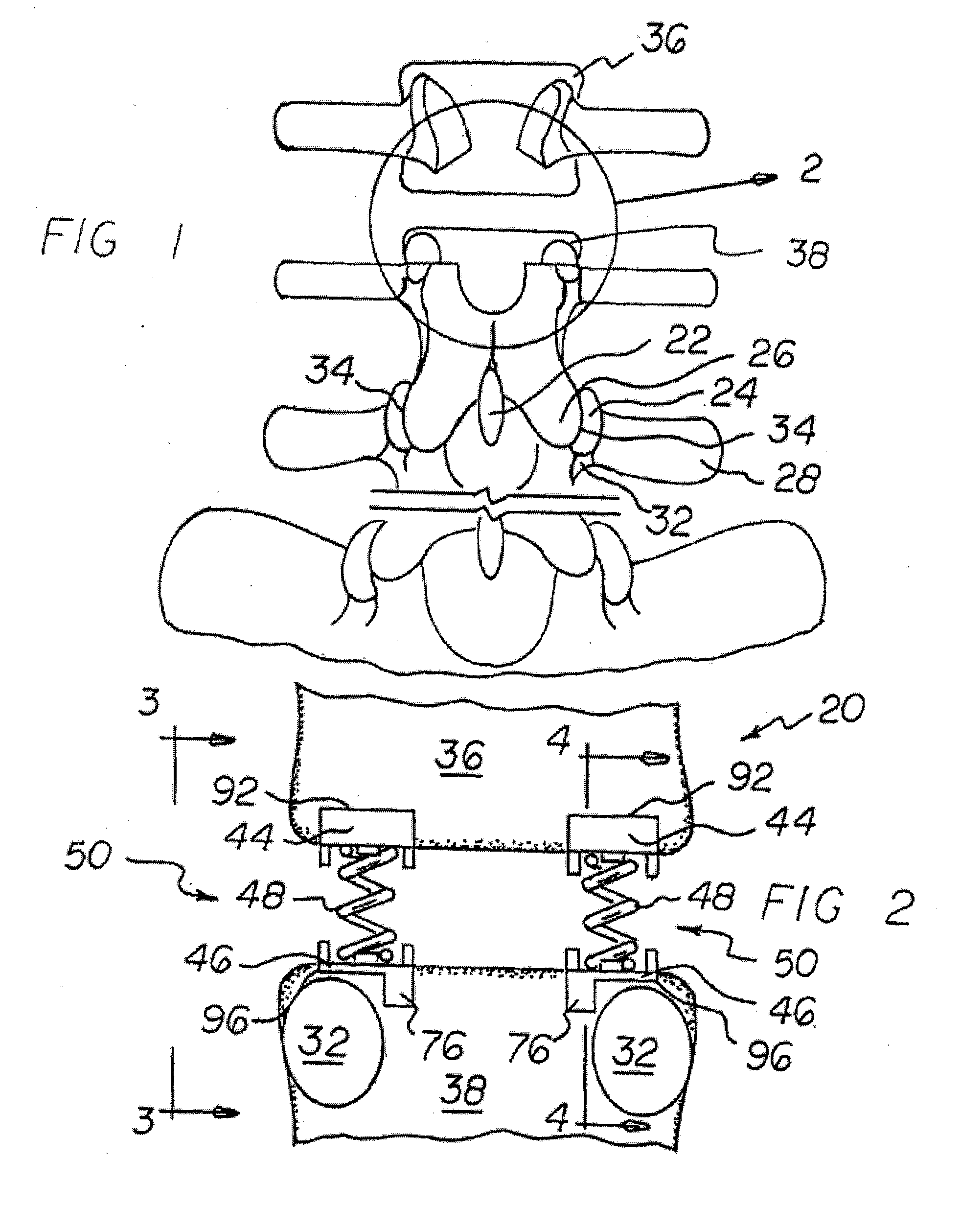
[0067]With reference now to FIG. 1, a posterior view of the lumbar region of a human spine is depicted. The implant of the present invention 20 is specifically adapted for insertion between adjacent vertebrae in this lumbar region, specifically vertebrae L3 throu...


PUM

PropertyMeasurementUnit
areasaaaaaaaaaa
forcesaaaaaaaaaa
absorb forcesaaaaaaaaaa

Abstract

Disclosed is an endoprosthetic implant for a human spinal disc. The structure of the implant allows it to be inserted posteriorly. This insertion is accomplished by performing a partial discectomy in the affected region. An intervertebral space is then created by removing the fibrocartilage between the facing surfaces of adjacent vertebrae. The implant is then inserted into the intervertebral space. The implant is thus adapted to replace damaged or worn intervertebral discs. Furthermore, the structure of the implant, and its posterior insertion, alleviate most spinal pathologies.

Description

CROSS-REFERENCES TO RELATED APPLICATIONS[0001]This application is a continuation of co-pending application Ser. No. 10 / 696,727, filed Oct. 28, 2003 and entitled “Vertebral Implants Adapted For Posterior Insertion” (now U.S. Pat. No. 7,485,134); which is a continuation-in-part of co-pending application Ser. No. 10 / 449,733, filed May 30, 2003 and entitled “Vertebral Implant with Dampening Matrix Adapted for Posterior Insertion” (now U.S. Pat. No. 7,052,515); which is a continuation-in-part of application Ser. No. 10 / 021,319, filed Dec. 7, 2001 and entitled “Vertebral Implant Adapted for Posterior Insertion” (now U.S. Pat. No. 6,572,653). The contents of all prior applications are incorporated herein by reference in their entirety.STATEMENT AS TO RIGHTS TO INVENTIONS MADE UNDER FEDERALLY SPONSORED RESEARCH OR DEVELOPMENT[0002]Not ApplicableREFERENCE TO A “SEQUENCE LISTING,” A TABLE, OR A COMPUTER PROGRAM LISTING APPENDIX SUBMITTED ON A COMPACT DISK[0003]Not ApplicableBACKGROUND OF THE ...

Claims


Application Information

Patent Timeline
Patent Type & Authority Applications(United States)
IPC IPC(8): A61F2/44A61B19/00A61BA61B17/70A61F2/00A61F2/30
CPCA61F2/30767A61F2310/00796A61F2002/30153A61F2002/30156A61F2002/30281A61F2002/30566A61F2002/30576A61F2002/30785A61F2002/30841A61F2002/443A61F2002/448A61F2230/0019A61F2230/0023A61F2230/0086A61F2310/00017A61F2310/00023A61F2/4425
Inventor SIMONSON, RUSH E.
Owner SIMONSON CYNTHIA JEANNE
Why Eureka
Try Eureka