Superabrasive grain setting method

a technology of superabrasives and setting methods, which is applied in the direction of grinding devices, manufacturing tools, other chemical processes, etc., can solve the problems of deteriorating grinding accuracy, and achieve the effect of precise grinding operations

Inactive Publication Date: 2009-06-04
TOYODA VAN MOPPES
View PDF6 Cites 6 Cited by
  • Summary
  • Abstract
  • Description
  • Claims
  • Application Information

AI Technical Summary

Benefits of technology

[0011]In the superabrasive grain setting method, the non-cylindrical area of the manufacturing mole CW on which diamond abrasive grains D are to be arranged in the grid pattern is developed into the circular-arc belt-like surface in the form of a plane, and the plurality of mounting points are rectified not to consecutively align in the circumferential direction of the circular-arc. By taking these simplified steps, it becomes possible to obviate such phenomena that each diamond abrasive grain behind tho

Problems solved by technology

In a grinding tool which is made by the use of such a manufacturing mold, a problems arise in that grinding accuracy is deteriorated because there occur either one of phenomena that abrasive grains behind in the rotational direction of those making consecutive grain lines do n

Method used


Image

  • Superabrasive grain setting method
  • Superabrasive grain setting method
  • Superabrasive grain setting method

Examples


Embodiment Construction

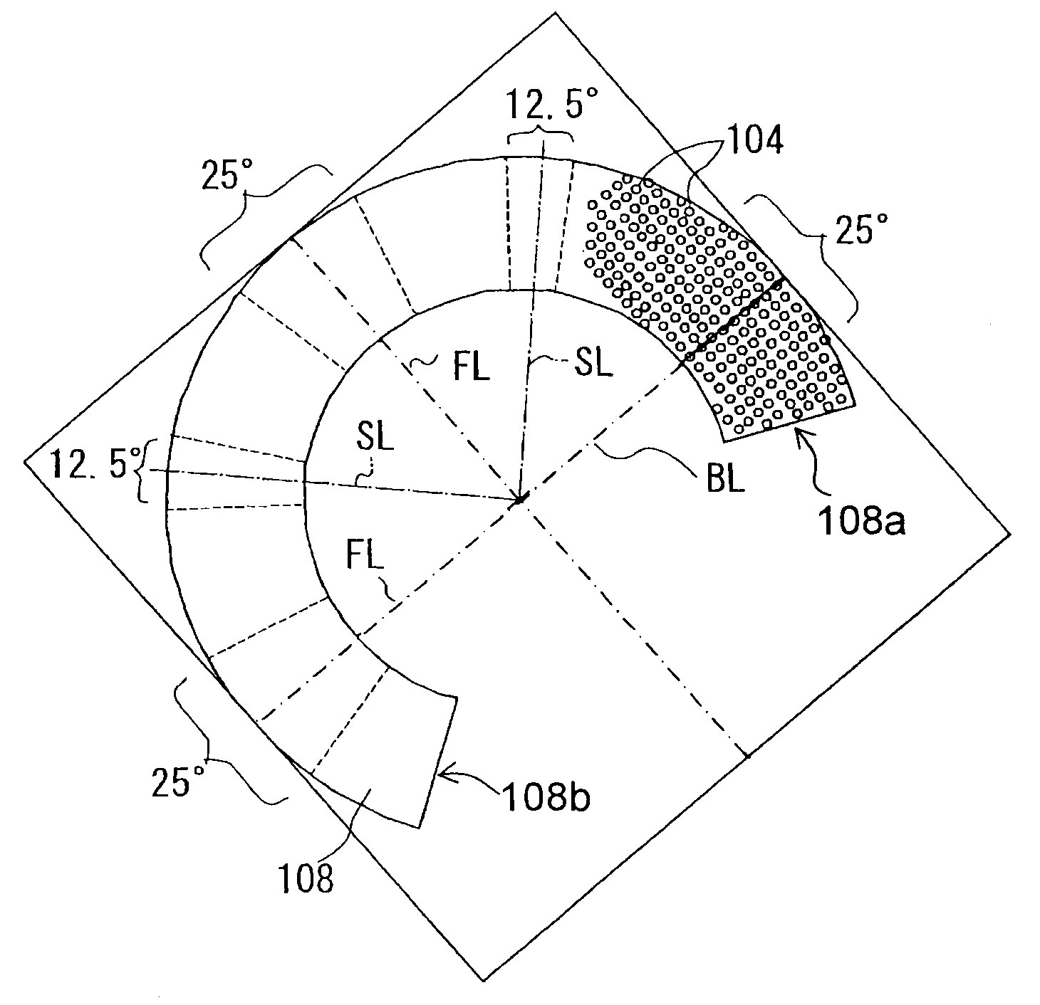
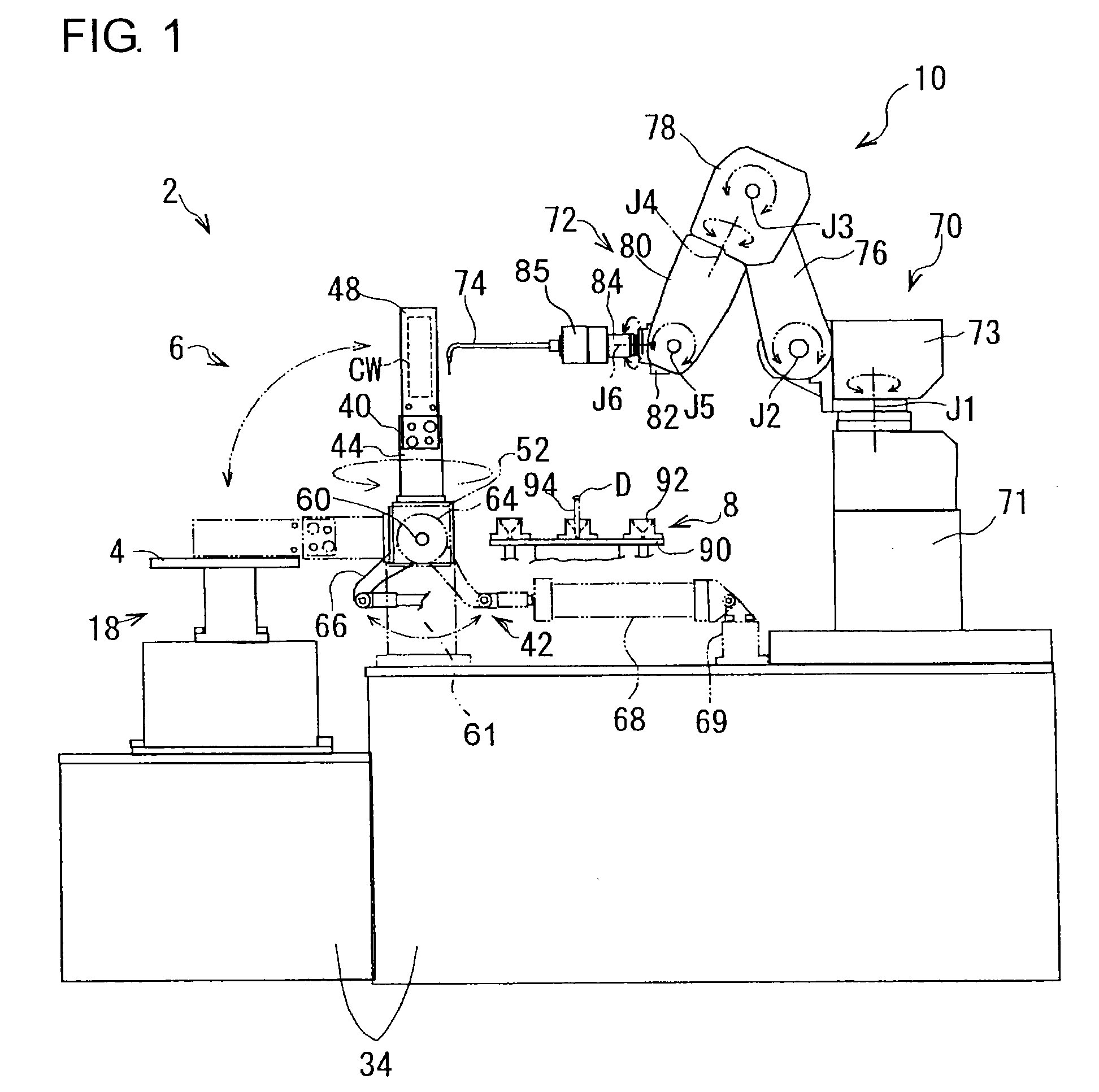
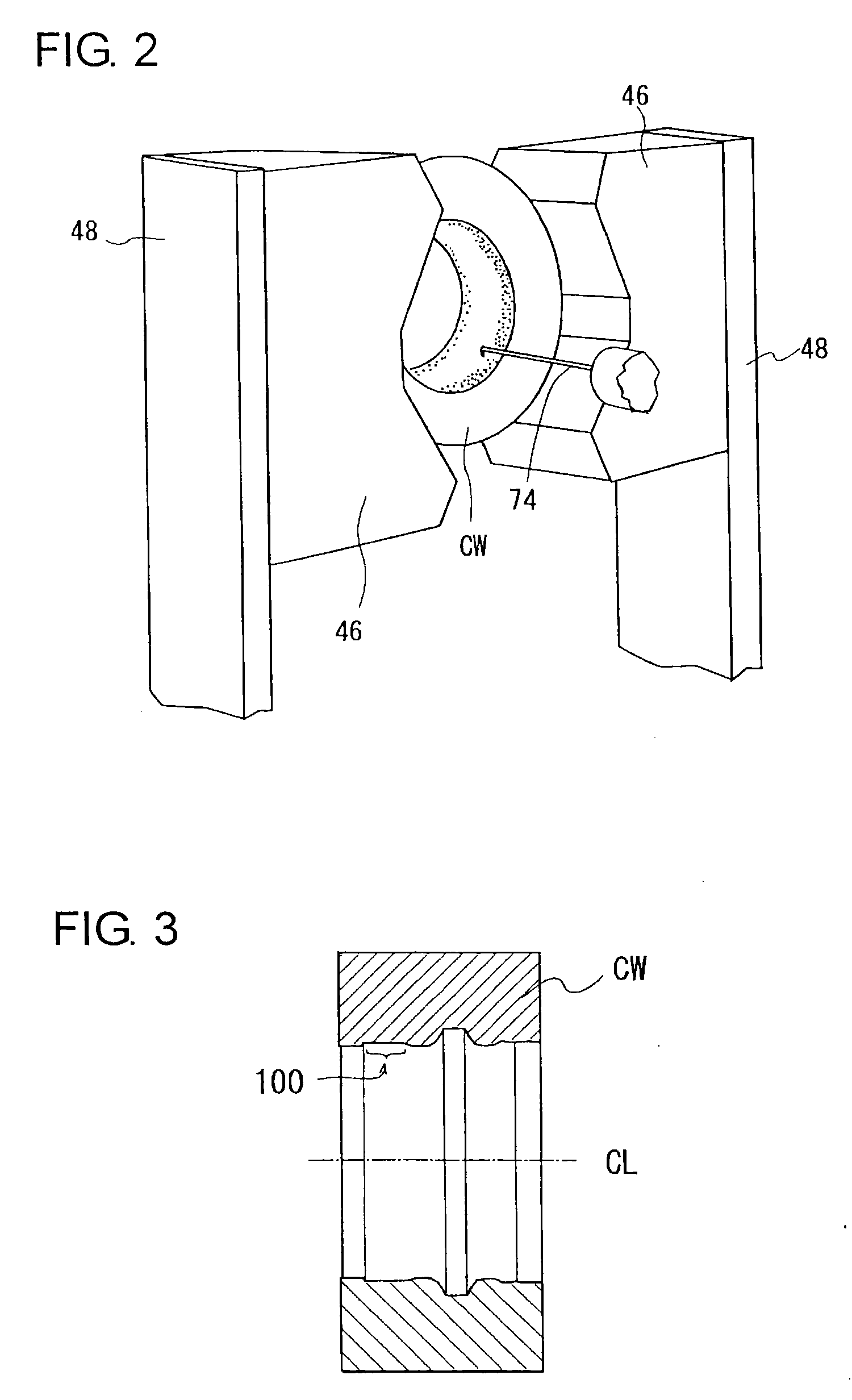
[0032]Hereafter, with reference to the accompanying drawings, description will be made regarding a superabrasive grain setting apparatus and a superabrasive setting method practiced by the apparatus in one embodiment according to the present invention. FIG. 1 is a schematic side view of the setting apparatus, and FIG. 2 is an enlarged perspective view showing the manner of setting superabrasive grains on a manufacturing mold in the setting apparatus. The manufacturing mold CW for use in manufacturing a grinding tool such as grinding wheel, truing tool, dressing tool or the like is made of, for example, carbon and takes a generally cylindrical form with flat end surfaces at opposite ends thereof. The setting of superabrasive grains is preformed on an internal surface of the manufacturing mold CW. This means that the manufacturing mold CW used here is a female-type mold for manufacturing a male-type grinding tool in a so-called “grain transfer method” wherein superabrasive grains arra...


PUM


Abstract

In a superabrasive grain setting method, a two-dimensionally developed coordinate preparation step is taken, wherein a non-cylindrical area of a mounting surface where a tangential line to the mounting surface in a plane including the axis of the manufacturing mold crosses with the axis of a manufacturing mold is developed into a circular-arc belt-like surface, and a plurality of mounting points are set on the circular-arc belt-like surface in a grid pattern in dependence on mounting positions for superabrasive grains. Then, a rectification step is taken, wherein the grid pattern of the mounting points is rectified in predetermined angular ranges so that the mounting points do not make consecutive point lines in the circumferential direction of the circular-arc belt-like surface. A mounting step is thereafter taken of mounting the superabrasive grains on the mounting surface of the manufacturing mold based on the grid pattern rectified at the rectification step.

Description

INCORPORATION BY REFERENCE[0001]This application is based on and claims priority under 35 U.S.C. 119 with respect to Japanese patent application No. 2007-312891 filed on Dec. 3, 2007, the entire content of which is incorporated herein by reference.BACKGROUND OF THE INVENTION[0002]1. Field of the Invention[0003]The present invention relates to a superabrasive setting method for mounting superabrasive grains on a manufacturing mold in order to arrange superabrasive grains on a grinding surface of a rotary grinding tool such as grinding wheel, truing tool, dressing tool or the like in manufacturing the rotary grinding tool.[0004]2. Discussion of the Related Art[0005]In the manufacturing of a rotary grinding tool such as grinding wheel, truing tool, dressing tool or the like, it is often the case that a grinding surface of the grinding tool are formed by the use of superabrasive grains such as diamond, CBN (Cubic Boron Nitride) or the like. In this case, the grinding tool should have su...

Claims


Application Information

Patent Timeline
IPC IPC(8): B24D13/00
CPCB24D18/0009B24D3/06
Inventor SAKAKIBARA, SADAOKOBAYASHI, KODOSHIMIZU, HIROYASUSUGITA, KAZUHIKO
Owner TOYODA VAN MOPPES
Why Eureka
Try Eureka