Lightning Protection System for a Wind Turbine Blade

Active Publication Date: 2009-06-04
LM GLASSFIBER
View PDF5 Cites 46 Cited by
  • Summary
  • Abstract
  • Description
  • Claims
  • Application Information

AI Technical Summary

Benefits of technology

[0011]According to a suitable embodiment, a layer of semiconducting material is provided between the inner conductor and the bedding insulation. Preferably, this semiconducting material has a thickness of 0.5-1 mm. The semiconducting material provides additional protection against flashovers by minimizing electrical field concentrations in the conductor.
[0012]According to a particular embodiment, the lightning receptor and the connection area between the lightning receptor and the lightning conductor are insulated by means of an insulating material, which is separate from the bedding material. This insulating material may e.g. be a shrink sle

Problems solved by technology

However, there is a risk of a flashover or sparkover from the lightning receptor or lightning conductor to areas in the blade, where water has accumulated, since water is electrically conductive.
In this case, lightning current heats up the water, which may cause a “steam explosion”.
This may result in pressure increases, which are sufficiently high to damage the blade.
The damages due to flashovers result in the blade having to be repaired or, in the worst ca

Method used


Image

  • Lightning Protection System for a Wind Turbine Blade
  • Lightning Protection System for a Wind Turbine Blade
  • Lightning Protection System for a Wind Turbine Blade

Examples


first embodiment

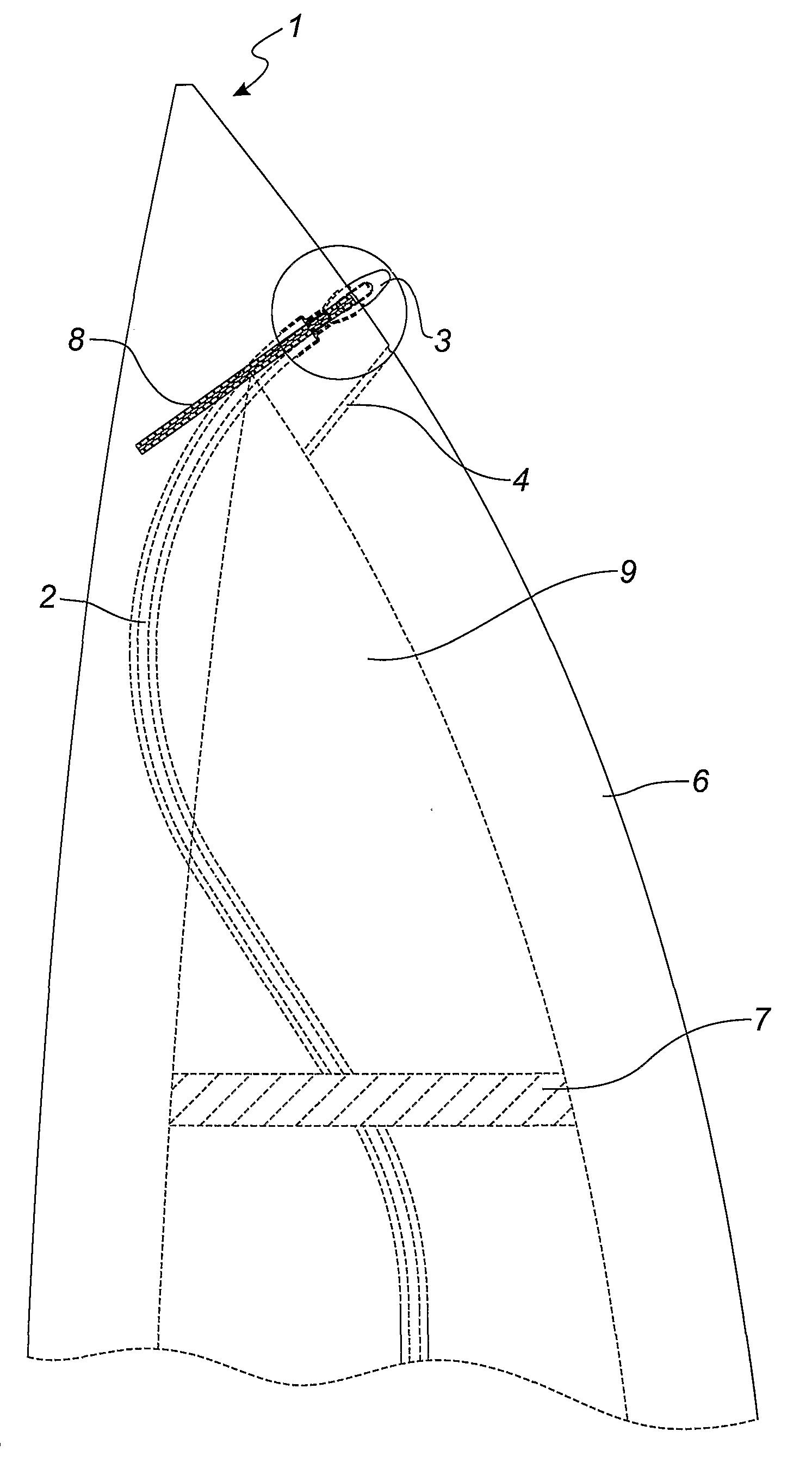
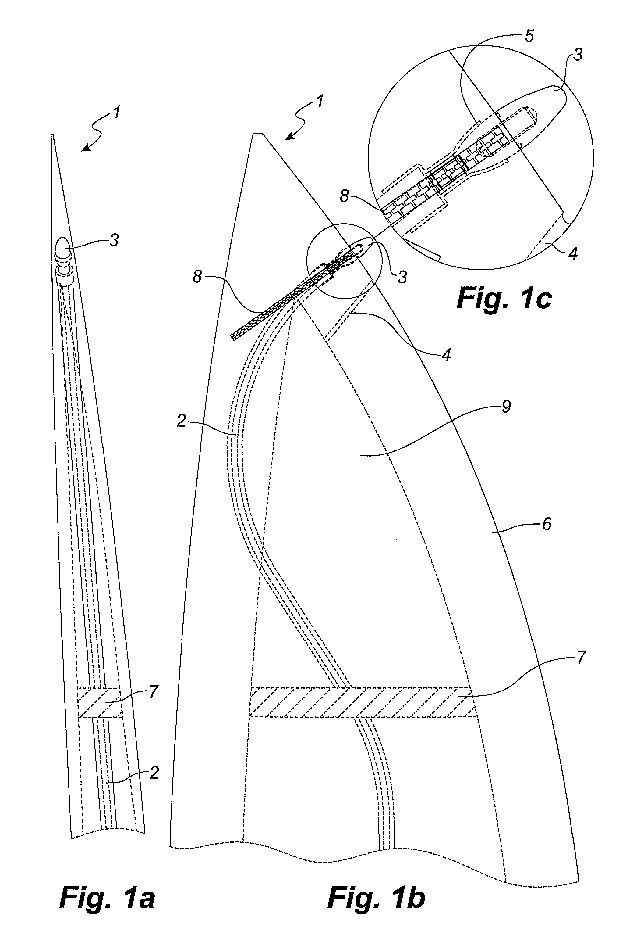
[0030]FIG. 1 shows a blade 1 according to the invention. According to this embodiment, a lightning receptor 3 is positioned at the tip end of the blade 1, said lightning receptor preferably, but not necessarily, being predominantly egg-shaped or formed like a so-called Franklin rod. The lightning receptor 3 is connected to a lightning conductor 2 extending substantially in the entire longitudinal direction of the blade 1 from the lightning receptor 3 at the tip of the blade 1 to the root area of the blade 1 at the rotor hub. Preferably, the lightning conductor portion is electrically connected to the hub, and lightning current from lightning striking the lightning receptor 3 can thus be led to earth via the lightning conductor 2 and the hub, said hub being earthed via a second lightning conductor (not shown) connected to an earth rod by means of e.g. the tower and the nacelle. Furthermore, one or more spark gaps may be provided between the lightning conductor 2 and the hub or betwee...

second embodiment

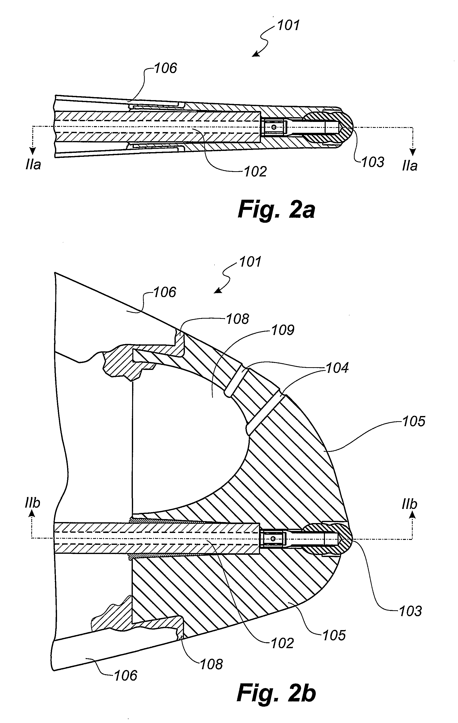
[0036]FIG. 2 shows a blade 101 according to the invention. The blade 101 according to this embodiment has a tip 105 formed as a solid body of e.g. polyurethane, PVC or fibre-reinforced polymer. The rest of the blade 101 is made of a shell body having a laminate shell 106. As in the embodiment shown in FIG. 1, the lightning protection system of the blade includes a lightning conductor 102 extending substantially in the entire longitudinal direction of the blade 101 from the root end at the rotor hub and to the tip end. The lightning conductor 102 is guided out of the cavity of the blade 101 and into a hole created in the tip 105 and matching the lightning conductor 102. The lightning conductor may be glued to this hole. The lightning conductor is connected with a substantially egg-shaped lightning receptor 103. The lightning receptor 103 is positioned at the surface of the tip 105 so that a small portion thereof projects from the surface. The position and the form of the receptor 103...

third embodiment

[0039]FIG. 3 shows a blade 201 according to the invention. The blade 201 according to this embodiment has a tip 205 formed as a substantially solid body of e.g. polyurethane, PVC or fibre-reinforced polymer as in the embodiment shown in FIG. 2. The rest of the blade 201 is made of a shell body having a laminate shell 206. As in the embodiments shown in FIG. 1 and FIG. 2, the lightning protection system of the blade 201 includes a lightning conductor 202 extending substantially in the entire longitudinal direction of the blade 201 from the root end at the rotor hub and to the tip end. The lightning conductor 202 is guided out of the cavity of the blade 201 and into a hole created in the tip 205 and fitting the shape of the lightning conductor 202.

[0040]The lightning conductor 202 is connected to a lightning receptor 203 having a rounded shape and positioned at the apex of the tip 205. The lightning receptor 203 is adapted so that there is a substantially smooth transition between the...


PUM


Abstract

The invention relates to a lightning protection system for a wind turbine blade, where the blade is a shell body made of a composite material and comprises a root area and a tip end. The lightning protection system comprises at least one lightning receptor arranged freely accessible in or on the shell unit surface on or in the immediate vicinity of the tip of the blade, and a lightning conductor made of electrically conductive material extending within the shell body along substantially the entire longitudinal direction of the blade. The lightning receptor and the lightning conductor are electrically connected by means of a connection area. The lightning conductor in its entire longitudinal direction as well as the connection area between the lightning conductor and the lightning receptor are electrically insulated in order to prevent lightning striking through the surface of the blade.

Description

TECHNICAL FIELD[0001]The present invention relates to a wind turbine blade with a lightning protection system, wherein the blade is a shell body made of a composite material and comprises a root area and a tip end, and wherein the lightning protection system comprises at least one lightning receptor arranged freely accessible in or on the shell body surface at or in the immediate vicinity of the tip of the blade, and a lightning conductor made of electrically conductive material extending within the shell body along substantially the entire longitudinal direction of the blade, and wherein the lightning receptor and the lightning conductor are electrically connected by means of a connection area.BACKGROUND ART[0002]It is known to provide blades with lightning protection systems to protect them from lightning strikes. As an example, WO 96 / 07825 discloses a lightning protection system, in which the tip of the blade is provided with a so-called lightning receptor made of an electrically...

Claims


Application Information

Patent Timeline
IPC IPC(8): H02G13/00
CPCF03D11/0033Y02E10/722Y02E10/721F03D80/30F05B2240/307Y02E10/72
Inventor HANSEN, LARS BO
Owner LM GLASSFIBER
Why Eureka
Try Eureka