Rotor construction in an electric motor

a technology of electric motors and rotors, applied in the direction of dynamo-electric machines, magnetic circuit rotating parts, magnetic circuit shapes/forms/construction, etc., can solve the problems of inability to guarantee adequate strength, additional manufacturing steps for shaft machining, etc., and achieve the effect of increasing manufacturing costs

Inactive Publication Date: 2009-06-04
BUHLER MOTOR GMBH
View PDF6 Cites 19 Cited by
  • Summary
  • Abstract
  • Description
  • Claims
  • Application Information

AI Technical Summary

Benefits of technology

[0007]An object of the invention is therefore to devise a rotor for an electric motor, in which a laminated rotor core can be fastened reliably and permanently to a rotor shaft, without significantly increasing manufacturing costs...

Problems solved by technology

This shaft machining requires additional manufacturing steps, without being able to guarantee adequate ...

Method used


Image

  • Rotor construction in an electric motor
  • Rotor construction in an electric motor
  • Rotor construction in an electric motor

Examples


Embodiment Construction

[0020]In describing preferred embodiments of the present invention illustrated in the drawings, specific terminology is employed for the sake of clarity. However, the invention is not intended to be limited to the specific terminology so selected, and it is to be understood that each specific element includes all technical equivalents that operate in a similar manner to accomplish a similar purpose.

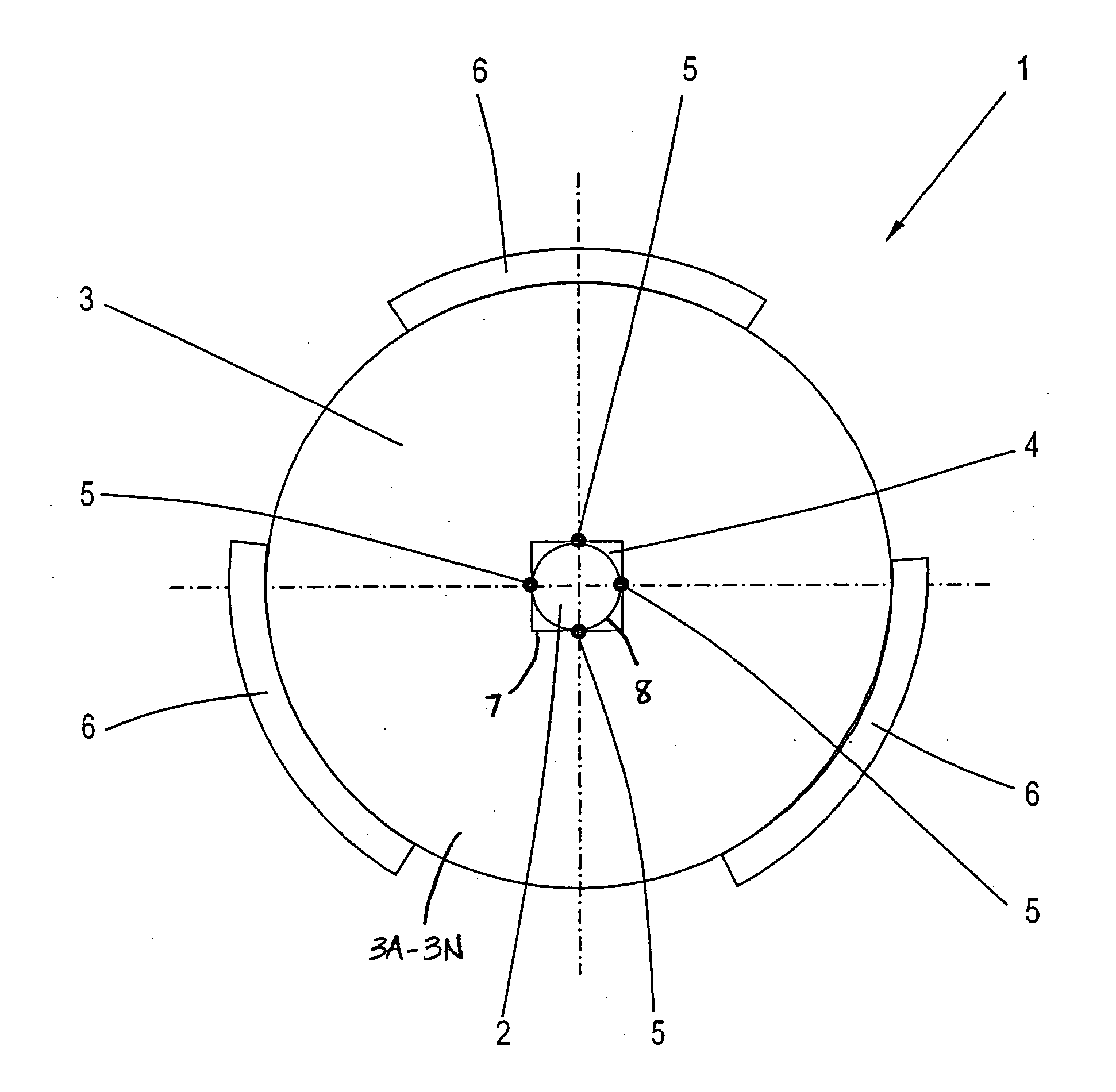
[0021]FIG. 1 is a schematic diagram of a rotor 1 in a welding device. To simplify matters, the welding device is shown with only three welding electrodes 6. In operation, the welding electrodes are applied to a laminated core 3 of the rotor 1.

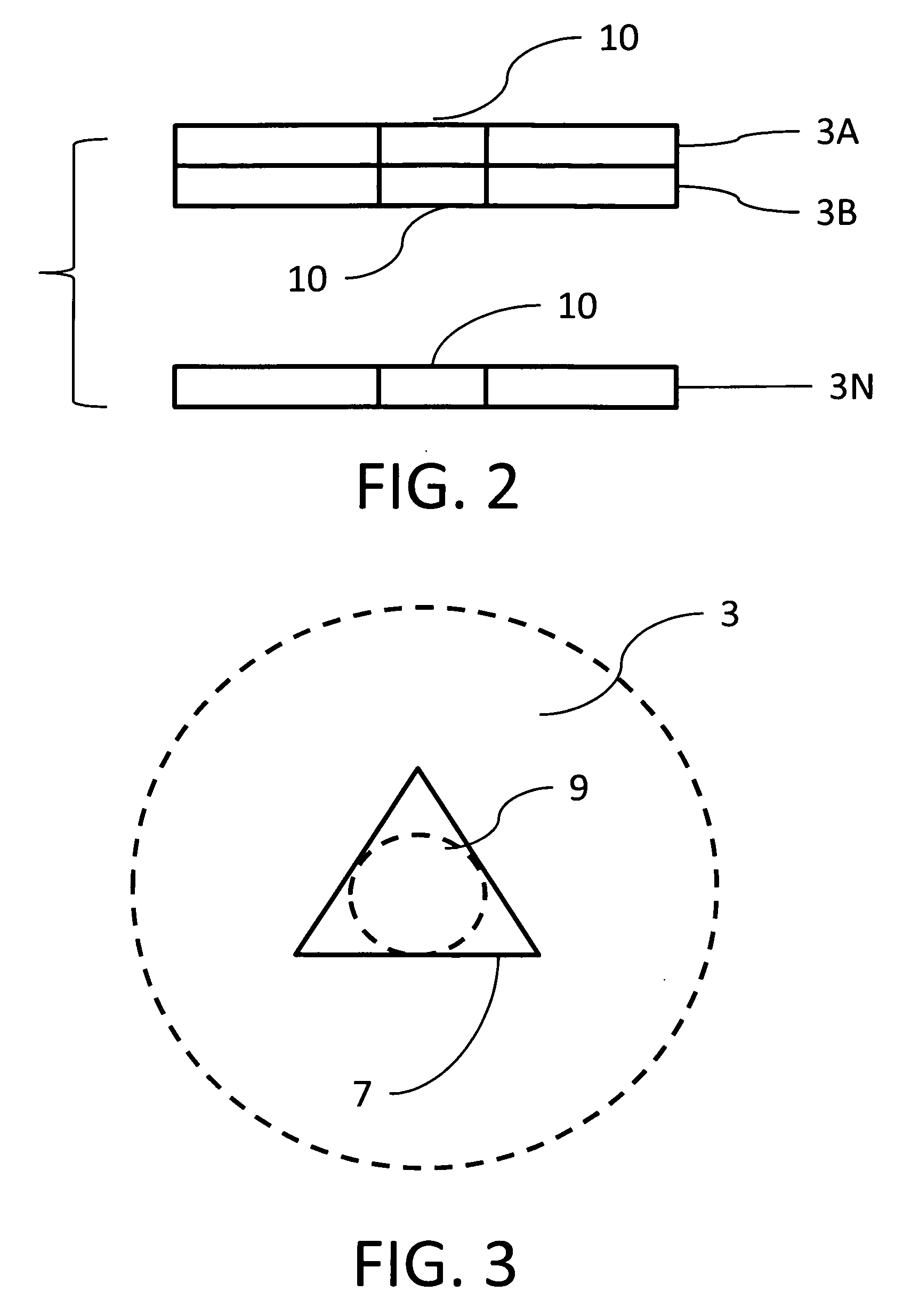
[0022]The laminated core is made up of a number of layers 3A-3N stacked one upon the other and laminated together is a conventional manner. In FIG. 1, the laminated core is viewed from above with the laminated core extending into the paper. The laminated core has a central cut out that extends through the full depth of the laminated layers that make ...


PUM


Abstract

A rotor of an electric motor with a cylindrical shaft and a magnetically conducting laminated core, the laminated core having a central shaft duct. The laminated core can be fastened reliably and permanently to the rotor shaft, without significantly increasing manufacturing costs. This task is accomplished by adhesively connecting the shaft to the laminated core in the area of its inside contour as by welding.

Description

CROSS-REFERENCE TO RELATED APPLICATIONS[0001](Not applicable)STATEMENT REGARDING FEDERALLY SPONSORED RESEARCH OR DEVELOPMENT[0002](Not applicable)BACKGROUND OF THE INVENTION[0003](1) Field of the Invention[0004]The invention concerns a rotor construction in an electric motor, in general, and to a rotor with a cylindrical shaft and a motor with a magnetically conducting laminated core with a central shaft duct, in particular.[0005](2) Description of Related Art[0006]A variety of fastening options for mounting a laminated core on a motor shaft are known. In the prior art, smooth shafts are often machined and provided with notches and burrs or knurling, in order to partially increase the shaft diameter. This shaft machining requires additional manufacturing steps, without being able to guarantee adequate strength of the force-fit connection when the connected shaft and laminated core are subjected to a high load.BRIEF SUMMARY OF THE INVENTION[0007]An object of the invention is therefor...

Claims


Application Information

Patent Timeline
IPC IPC(8): H02K1/28
CPCH02K1/28H02K1/278
Inventor SCHIEWECK, ARNOSTRUEBER, JUERGEN
Owner BUHLER MOTOR GMBH
Why Eureka
Try Eureka