Information display system for a vehicle

a technology for information display and vehicles, applied in the field of rearview mirror assemblies, can solve the problems of increased vibration in the casing and reflective element, increased difficulty in assembling the rearview mirror, and increased complexity of the rearview mirror assembly process, so as to achieve the effect of improving the mounting arrangemen

Inactive Publication Date: 2009-06-04
DONNELLY CORP
View PDF13 Cites 41 Cited by
  • Summary
  • Abstract
  • Description
  • Claims
  • Application Information

AI Technical Summary

Benefits of technology

[0008]The present invention provides a rearview mirror assembly incorporating a modular structure which provides for mounting either prismatic or electrochromic reflective elements, as well as an improved mounting arrangement for information displays.
[0013]In yet further aspects, a frame is mounted to the display element, which mounts the display element onto the carrier over the body and the cavities. For example, the frame may include a base wall mounted to the display element, with the base wall including a plurality of openings corresponding to and aligning with the cavities of the body. The openings expose areas of the display element for displaying the indicia. In preferred form, the frame includes recessed landing surfaces extending around each of the openings. The body includes projecting perimeter walls around each of the cavities, with the perimeter walls seating on the landing surfaces of the frame to isolate each cavity in each of the areas of the display plate member to substantially reduce light leakage between the respective light assemblies.
[0018]Advantages provided by this invention include a structure having modular elements, which comprise common components for assembling a rearview mirror assembly, regardless of whether an electrochromic / electro-optic mirror assembly or a prismatic mirror assembly is desired. Additionally, the invention provides a more stable actuator for the prismatic mirror assembly design, which improves the vibration characteristics of and thus the visibility of reflected images in the reflective element assembly. Further, the invention provides improved space economizing support for various electronic and / or electrical features included in the assembly, as well as improved information display visible by drivers and passengers in the vehicle in which the assembly is mounted.

Problems solved by technology

However, these actuators often exhibit rotational movement between the casing and the bracket which can lead to increased vibration in the casing and reflective element.
In addition, space within the prismatic mirror casing is limited by the actuator which moves within the casing.
In addition, because of the increase in included devices as well as the number of combined features, the rearview mirror assembly process has become more difficult and complex.
However, such reinforcements reduce the potential available space in the mirror casing.

Method used


Image

  • Information display system for a vehicle
  • Information display system for a vehicle
  • Information display system for a vehicle

Examples


first embodiment

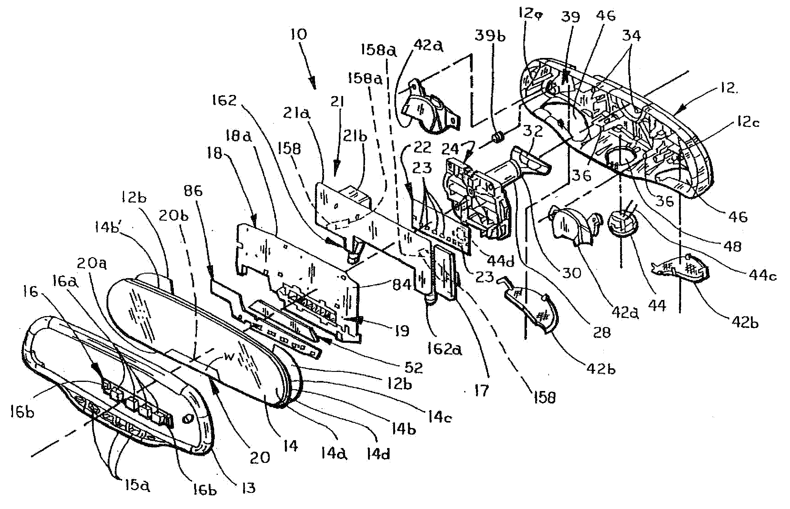
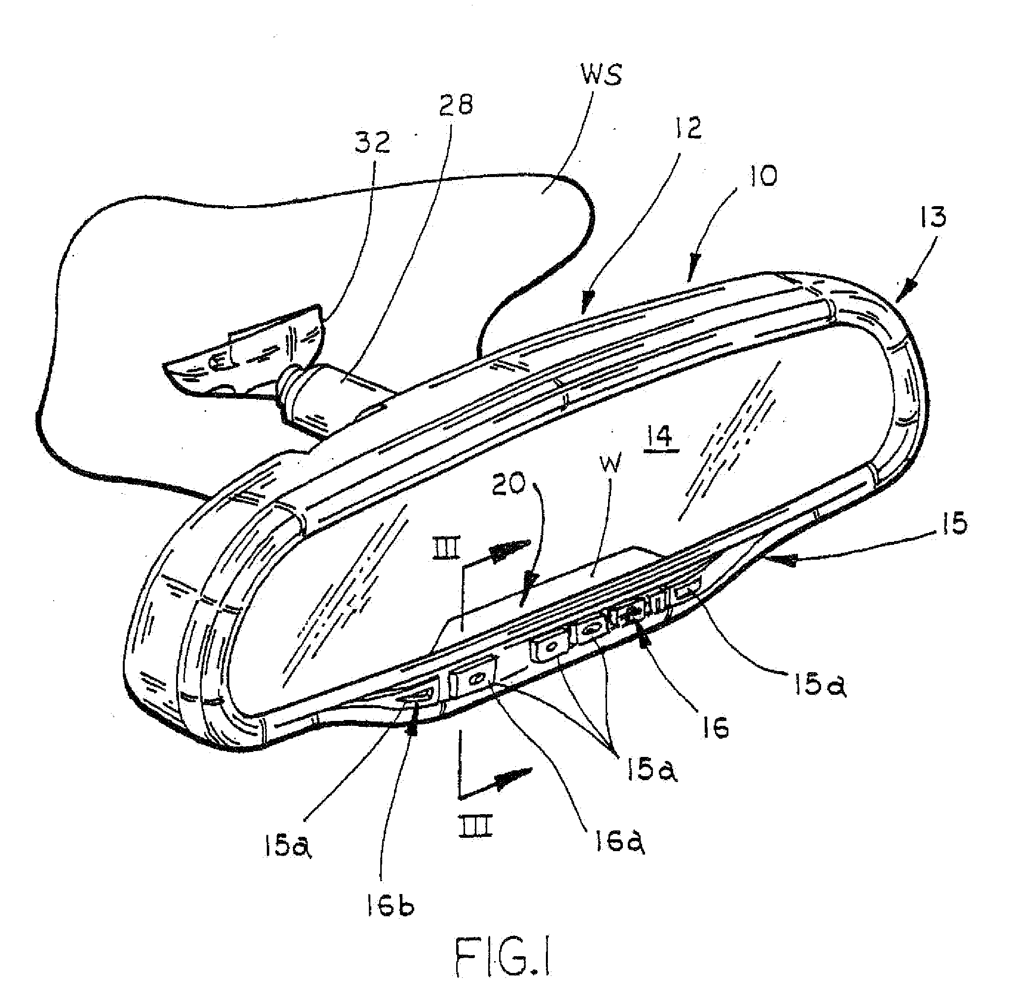
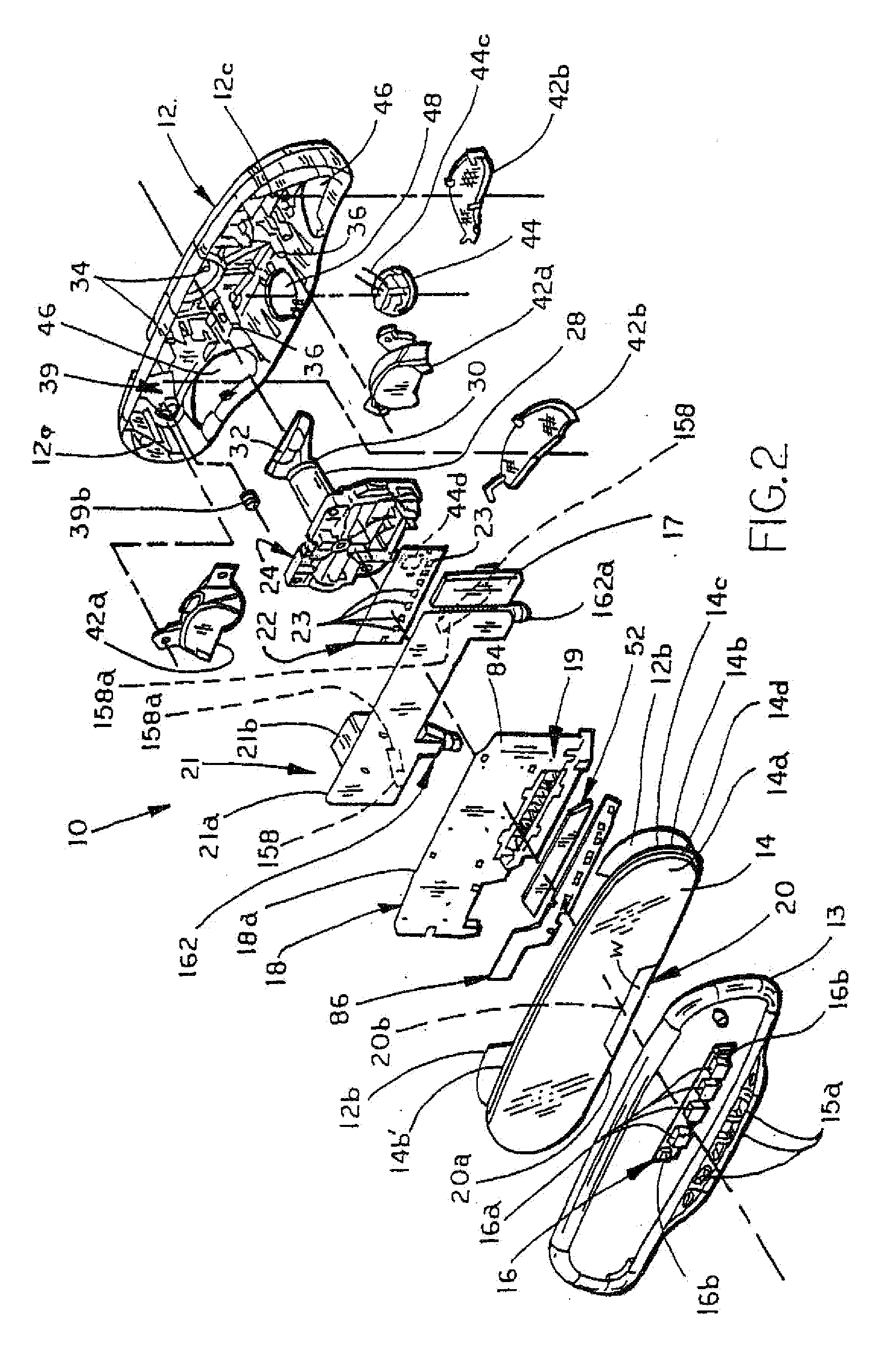
[0070]Referring now to FIG. 1, an interior rearview mirror assembly 10 for vehicles of the present invention includes an improved structure incorporating modular elements or units and a light module for illuminating an information display area 20 of assembly 10. In the illustrated embodiment, assembly 10 is adapted to be releasably coupled or secured to the front windshield WS of a vehicle below the headliner header section of the interior roof in position for viewing by the driver in a direction generally rearwardly of the vehicle. It should be understood that assembly 10 may also be mounted to the headliner or to other structures of the vehicle.

[0071]Mirror assembly 10 includes a mirror case or housing 12, a bezel 13, and a mirror reflective element 14. Bezel 13 includes an enlarged chin area 15 positioned below the viewing area of reflective element 14, with a plurality of openings 15a (FIG. 2) for receiving a user actuatable interface; for example user actuatable buttons 16a and...

case 12

[0072]Case 12 is mounted to windshield WS by mounting bracket 24 and support 28 (FIGS. 1, 2, 3, and 5). Referring to FIGS. 5 and 5A-5E, mounting bracket 24 includes a rearwardly extending ball mount 26 which mounts mirror assembly 10 onto a support arm 28. Bracket 24 is preferably formed from a resinous polymeric or plastic material and, more preferably, from a mineral filled polypropylene, such as glass or mineral filled nylon, for example RENY 252A. Ball mount 26 is preferably a zinc ball stud and preferably insert molded into bracket 24. Bracket 24 is rigidly mounted to rear wall 38 of case 12 preferably by heat staking onto projecting members, such as mounting bosses 34 and 36 (FIGS. 4 and 4A) which project outwardly from back wall 38 of case 12 and which extend into openings 25 provided at each corner of bracket 24 (FIGS. 5 and 5A-B). In addition, bracket 24 includes outwardly extending flanges 24a each having an elongate opening 24b and an elongate opening 24c at its upper per...

embodiment 10

[0081]In the illustrated embodiment 10, window W comprises a generally trapezoidal area, which is preferably located at a central lower edge 20a of reflective element 14. However, it should be understood that the display area can be located elsewhere, for example along an upper edge or side edge of reflective element 14. Display area 20 is used to provide information, such as by way of alpha-numeric indicia or symbolic or graphical indicia, such as icons, including for example passenger safety information, such as Passenger Side Inflatable Restraint (PSIR) status or Supplemental Inflatable Restraint (SIR) status.

[0082]The luminous intensity of the Passenger Side Inflatable Restraint display that indicates the status of activation / deactivation of passenger-side airbags (or of Side-airbag Inflatable Restraint display in the case where the vehicle is equipped with side airbags) should be sufficiently intense so as to be readily visible by vehicle occupants, even under high ambient ligh...


PUM

PropertyMeasurementUnit
thicknessaaaaaaaaaa
thicknessaaaaaaaaaa
thicknessaaaaaaaaaa

Abstract

An interior rearview mirror assembly for vehicles includes a mirror case having a reflective element and a carrier positioned in the mirror case. The mirror case is adapted to mount to a vehicle. The reflective element includes a substrate, with a reflective coating on one side of the substrate, and a window therethrough. The carrier has a display element for displaying one or more indicia through the window to define a display area on the reflective element. The carrier comprises a plate member, with a first portion and a second portion offset rearwardly from the reflective element and from the first portion. The second portion includes the display element. Preferably, the interior rearview mirror assembly further includes at least one light assembly for displaying the indicia through said window so that it is visible to an occupant of the vehicle.

Description

CROSS REFERENCE TO RELATED APPLICATIONS[0001]This application is a continuation of U.S. patent application Ser. No. 10 / 879,574, filed Jun. 28, 2004, now U.S. Pat. No. 7,488,080, which is a continuation of U.S. patent application Ser. No. 10 / 328,886, filed Dec. 24, 2002, now U.S. Pat. No. 6,756,912, which is a continuation of U.S. patent application Ser. No. 09 / 988,210, filed Nov. 19, 2001, now U.S. Pat. No. 6,501,387, which is a continuation of U.S. patent application Ser. No. 09 / 448,700, filed on Nov. 24, 1999, now U.S. Pat. No. 6,329,925, which are incorporated by reference herein in their entireties.TECHNICAL FIELD AND BACKGROUND OF THE INVENTION[0002]The present invention relates to rearview mirror assemblies and, more particularly, to a modular variable reflectance interior rearview mirror assembly for use in vehicles incorporating information displays and controls for various electronic or electrical functions.[0003]Variable reflectance interior rearview mirror assemblies incl...

Claims


Application Information

Patent Timeline
Patent Type & Authority Applications(United States)
IPC IPC(8): G02F1/19B60R1/08B60R1/12B60R11/00B60R11/02G02B27/01G06Q20/00
CPCB60R1/12B60R11/02B60R11/0217H04R2499/13B60R11/0247B60R2011/0026B60R2011/0033B60R11/0241B60Q3/258G02B5/08G02B17/00B60R1/086B60R1/088B60R1/1207B60R2001/1223G10K2210/1282G10L21/028
Inventor SKIVER, TIMOTHY G.MCCAW, JOSEPH P.UKEN, JOHN T.DELINE, JONATHAN E.LYNAM, NIALL R.
Owner DONNELLY CORP
Why Eureka
Try Eureka