Distortion compensation circuit and method

a compensation circuit and distortion technology, applied in the field of distortion, can solve the problems of signal distortion degrading the system performance, non-flat in-band amplitude and group delay response, and increase the transmit power and/or transmit bandwidth, and achieve the effect of reducing the differen

Inactive Publication Date: 2009-06-04
HER MAJESTY THE QUEEN & RIGHT OF CANADA REPRESENTED BY THE MIN OF IND THROUGH THE COMM RES CENT
View PDF5 Cites 32 Cited by
  • Summary
  • Abstract
  • Description
  • Claims
  • Application Information

AI Technical Summary

Benefits of technology

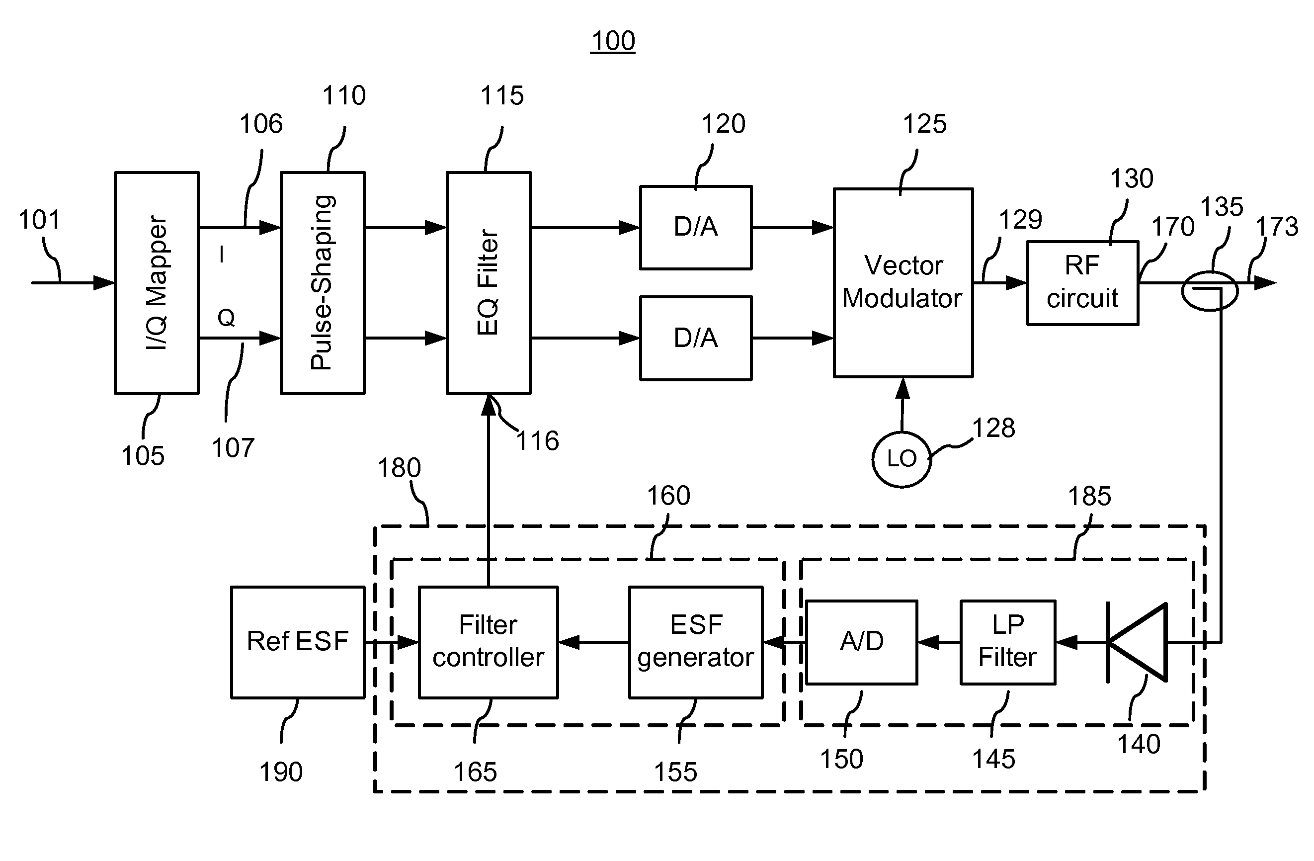
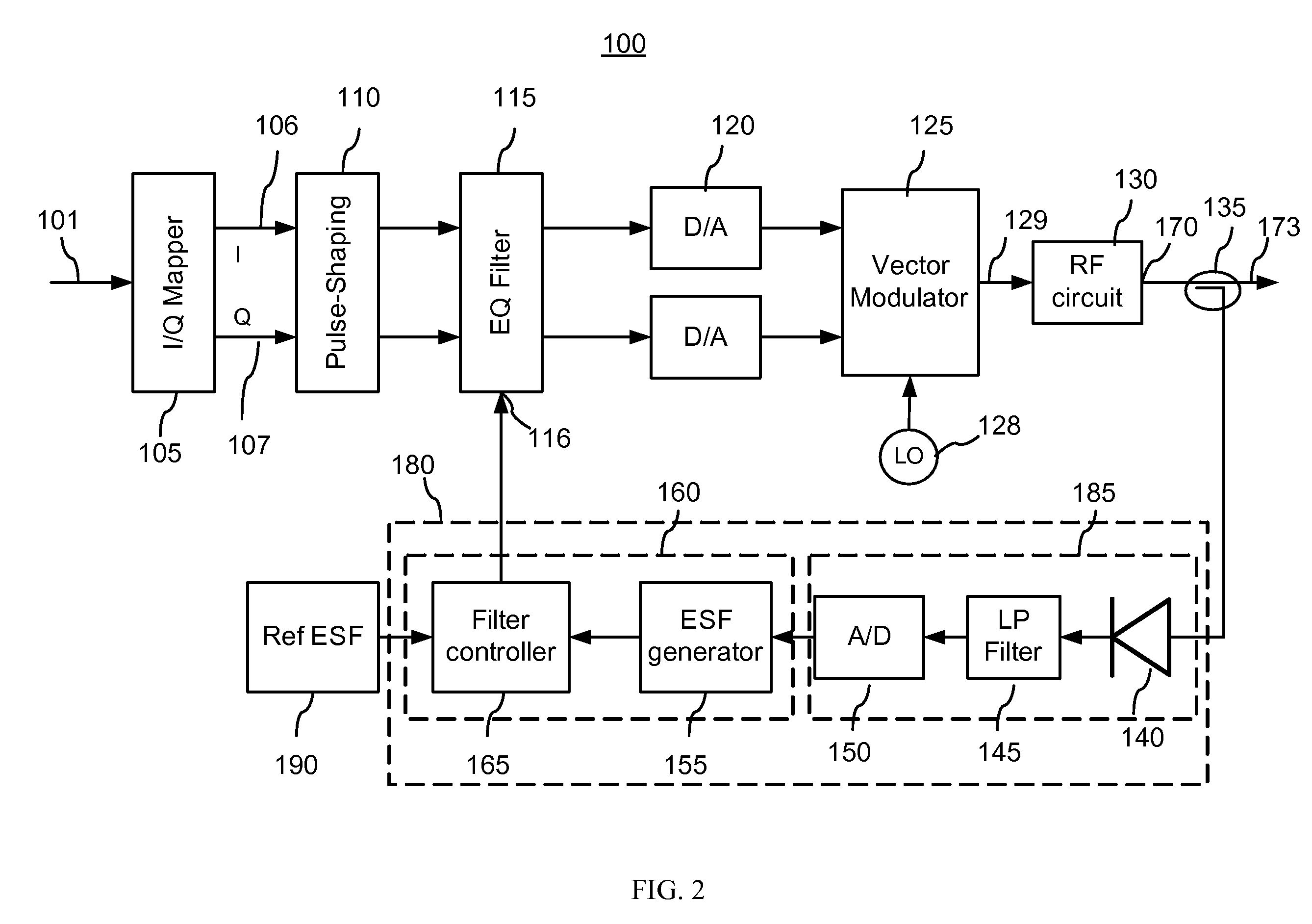
[0012]In accordance with the invention, there is provided a distortion compensation circuit for compensating in-band distortion experienced by a modulated signal in a communication path. The circuit comprises an input port for providing the modulated signal, a linear filter for adaptively modifying a spectrum of the modulated signal, the linear filter having a control port for receiving a set of filter coefficients defining a frequency response of the linear filter, an output port for providing an output signal comprising at least a portion of the modulated signal after the propagation thereof through the communication path and the linear filter, a reference circuit for providing a reference envelope statistical function (ESF) for the modulated signal prior to the propagation thereof through the communication path, and a filter control circuit coupled between the output port and the control port of the linear filter for adjusting the frequency response thereof in dependence upon the output signal. The filter control circuit comprises: a sampling circuit for sampling at least a portion of the output signal to provide a plurality of signal envelope samples, an ESF estimator for estimating an output ESF based on the plurality of signal samples, a filter generator for generating the filter coefficients based on the reference ESF and the output ESF, and for providing said filter coefficients to the control port of the linear filter for adjusting the frequency response thereof so as to reduce a difference between the reference ESF and the output ESF.
[0014]In accordance with one aspect of this invention, there is further provided a method for compensating in-band distortion experienced by a modulated signal in a communication path, which comprises: a) providing a reference envelope statistical function (ESF) for the modulated signal; b) providing a linear filter having a frequency response defined by a set of filter coefficients; c) passing the modulated signal through the linear filter and the communication path to obtain an output signal; d) estimating an output ESF for the output signal; and, e) adjusting one or more of the filter coefficients of the linear filter so as to decrease a difference between the reference ESF and the output ESF.
[0016]In accordance with one aspect of this invention, there is further provided a method for compensating in-band distortion experienced by a modulated signal in a communication path, which comprises: a) providing a reference envelope statistical function (ESF) for the modulated signal; b) providing a linear filter having a frequency response defined by a set of adjustable filter coefficients; c) providing a first set of filter coefficients to the linear filter; d) passing the modulated signal through the linear filter and the communication path to obtain an output signal; e) estimating an output ESF for the output signal; f) obtaining a first objective function value based on the output ESF and the reference ESF, and saving said objective function value in memory; c) providing a second set of filter coefficients to the linear filter, and repeating steps (d)-(f) to obtain a second objective function value; d) generating a third set of filter coefficients based on the first and second objective function values so as to reduce a difference between the reference ESF and the output ESF.

Problems solved by technology

In many communication systems, such as those employing wideband signals like spread spectrum or very high data rate links, as well as those with stringent constraints in out-of-band spurious levels, the overall channel frequency response results in non-flat in-band amplitude and group delay responses.
Such distortions in the frequency response degrade the link performance leading to a requirement for an increased transmit power and / or higher transmit bandwidth.
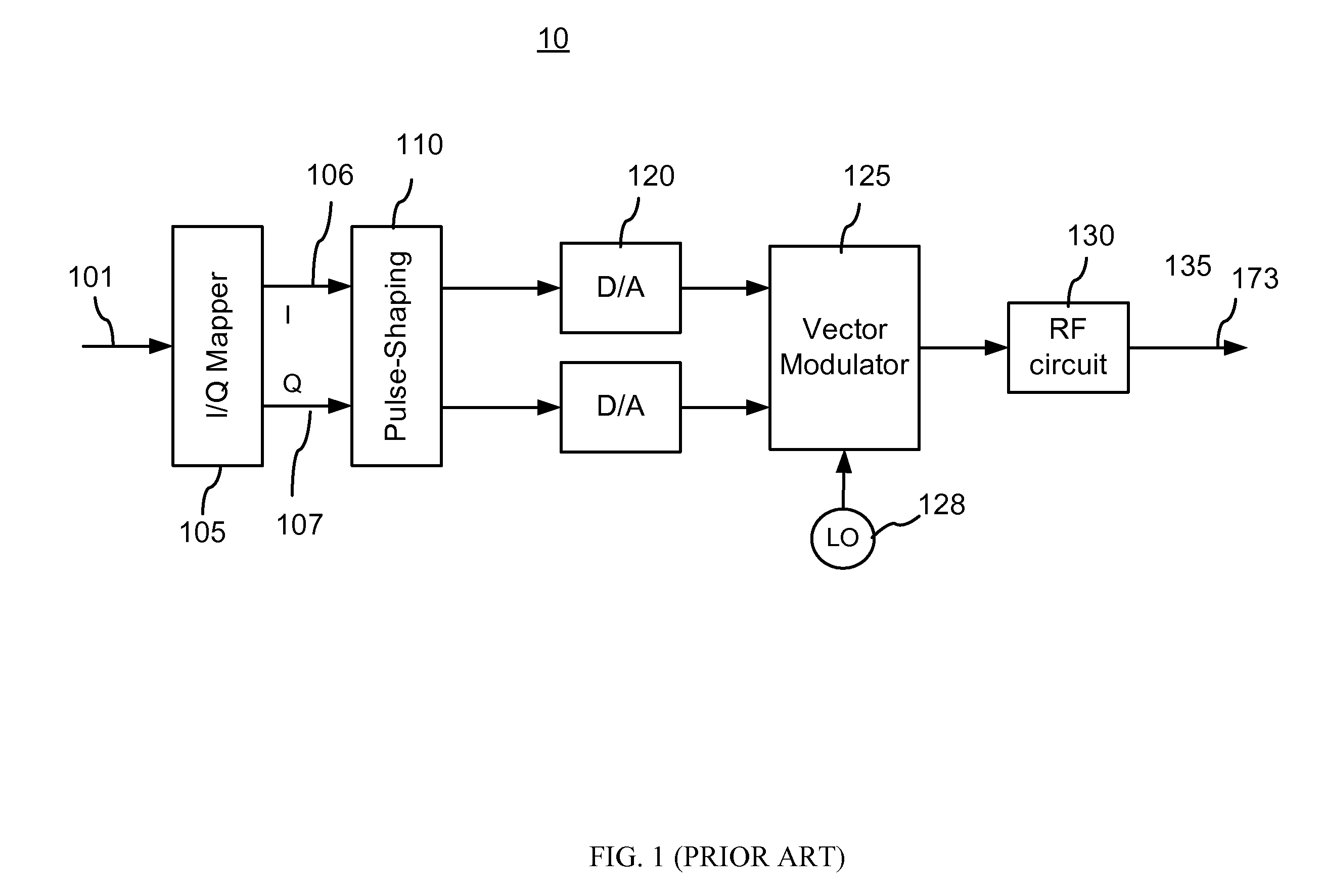
Such conditioning typically involves pulse shaping, one or more stages of frequency up-conversion each followed by filtering and amplification before being fed to an antenna, wherein a high-frequency communication signal goes through a number of devices and components, which frequency amplitude and group delay responses may not be flat, resulting in the signal distortion degrading the system performance.
The RF circuit 130 may introduce various distortions in the RF signal that degrade the communication system performance.
One cause of such distortions is the non-linearity of an amplification characteristic of the power amplifier (PA) that may be included in the RF circuit 130, which introduces non-linear distortions in the amplified signal.
These non-linear distortions divert some of the energy from a desired frequency channel into adjacent frequency channels, thereby resulting in a loss of performance within a desired frequency channel as well as the creation of interference within adjacent frequency channels.
Although the method described in the '241 patent has many attractive features and works well in reducing the detrimental effect of the PA non-linearity when such nonlinearities are constant over frequency, it is not directly applicable to linear in-band distortions in the RF circuit 130 where the level of distortion is frequency dependent, such as non-uniform group delay and / or amplitude frequency response of the RF circuit.
Contrary to that, the linear in-band distortions, rather than change the intensity of the signal, distort its spectrum, and therefore there appears to be no direct and clear way of deducing such distortions from the shape of the CDF.
Unfortunately, these linear in-band distortions of the transmitted signal become a significant source of errors, especially for broad-band transmission systems operating at high carrier frequencies, e.g. in the wavelength range of a few centimeters or less.
However, this approach requires selecting components with tight tolerances, which may be significantly more expensive or may not be available for circuits operating at very high frequencies, such as in the GHz range and above.
However, in addition to requiring more complex calibration procedures, such look-up tables are inevitably approximate and their use typically results in insufficient compensation of in-band distortion for some applications.

Method used


Image

  • Distortion compensation circuit and method
  • Distortion compensation circuit and method
  • Distortion compensation circuit and method

Examples


Embodiment Construction

[0039]In the following detailed description, numerous specific details are set forth in order to provide a thorough understanding of the invention. However it will be understood by those of ordinary skill in the art that the present invention may be practiced without these specific details. In other instances, well-known methods, procedures, components and circuits have not been described in detail so as not to obscure the present invention.

[0040]Some portions of the detailed description that follows hereinbelow are presented in terms of algorithms and symbolic representations of operations on data bits or binary digital signals within a computer memory. These algorithmic descriptions and representations may be the techniques used by those skilled in the data processing arts to convey the substance of their work to others skilled in the art.

[0041]Unless specifically stated otherwise, as apparent from the following discussions, it is appreciated that throughout the specification disc...


PUM


Abstract

The invention relates to methods and circuits for compensating linear in-band distortions such as those occurring in RF circuits of broad band communication systems. A low-rate sampling is used to collect statistical information about a modulated signal after it passed through the distorting circuits, which is then compared to reference statistical information for the modulated signal to iteratively adjust a frequency response of an equalizing linear filter inserted into the signal path so as to compensate for the distortions.

Description

CROSS-REFERENCE TO RELATED APPLICATIONS[0001]The present invention claims priority from U.S. Provisional Patent Application No. 61 / 025,928, filed Feb. 4, 2008, entitled “Type-based estimation of frequency response equalizer's coefficients”, which is incorporated herein by reference. It is a continuation in part of U.S. patent application Ser. No. 11 / 702,523, filed Feb. 6, 2007, entitled “Self-calibrating multi-port circuit and method”, which claims priority from U.S. Provisional Patent Application No. 60 / 765,744, filed Feb. 7, 2006, entitled “Type-based direct transmitter self-calibration technique”, and U.S. Provisional Patent Application No. 60 / 811,408, filed Jun. 7, 2006, entitled “Type-based subsystem calibration technique”, which are incorporated herein by reference for all purposes.TECHNICAL FIELD[0002]The present invention relates generally to systems and methods for transmission of wireless signals in the presence of distortion, and in particular to distortion compensation c...

Claims


Application Information

Patent Timeline
Patent Type & Authority Applications(United States)
IPC IPC(8): H04L25/49
CPCH04L27/364
Inventor HUANG, XINPINGCARON, MARIO
Owner HER MAJESTY THE QUEEN & RIGHT OF CANADA REPRESENTED BY THE MIN OF IND THROUGH THE COMM RES CENT
Why Eureka
Try Eureka