Supercharge Your Innovation With Domain-Expert AI Agents!

Structure for mounting a filter in a compressor

a technology for mounting structures and filters, which is applied in the direction of filtration separation, positive displacement liquid engines, separation processes, etc., can solve the problems of wire mesh filters being removed from the capillary and not providing a detailed description of the structure for connecting the capillary

Inactive Publication Date: 2009-06-04
TOYOTA IND CORP
View PDF6 Cites 8 Cited by
  • Summary
  • Abstract
  • Description
  • Claims
  • Application Information

AI Technical Summary

Benefits of technology

The present invention provides a structure for mounting a filter in a compressor. The structure includes a mounting member, a receiving hole, a first fitting portion, a second fitting portion, a fluid passage, and a clearance. The mounting member is connected to the filter, the receiving hole is formed in the housing of the compressor for receiving the mounting member, the filter has a filter screen and a holding portion for holding the filter screen, the first fitting portion is formed on the inner circumferential surface of the holding portion, the second fitting portion is formed on the outer circumferential surface of the mounting member for fitting relation with uneven surface to the first fitting portion, the fluid passage is formed in the housing, and the clearance is formed between the outer circumferential surface of the holding portion and the inner circumferential surface of the receiving hole. The technical effect of this structure is that it provides a secure and reliable mounting of the filter in the compressor, ensuring proper functioning and durability of the filter.

Problems solved by technology

However, the former Publication No. 55-29040 does not provide a detailed description about the structure for connecting the capillary and the wire mesh filter.
Therefore, there is a fear that the wire mesh filter may be removed from the capillary due to vibration of the compressor.

Method used


Image

  • Structure for mounting a filter in a compressor
  • Structure for mounting a filter in a compressor
  • Structure for mounting a filter in a compressor

Examples


first embodiment

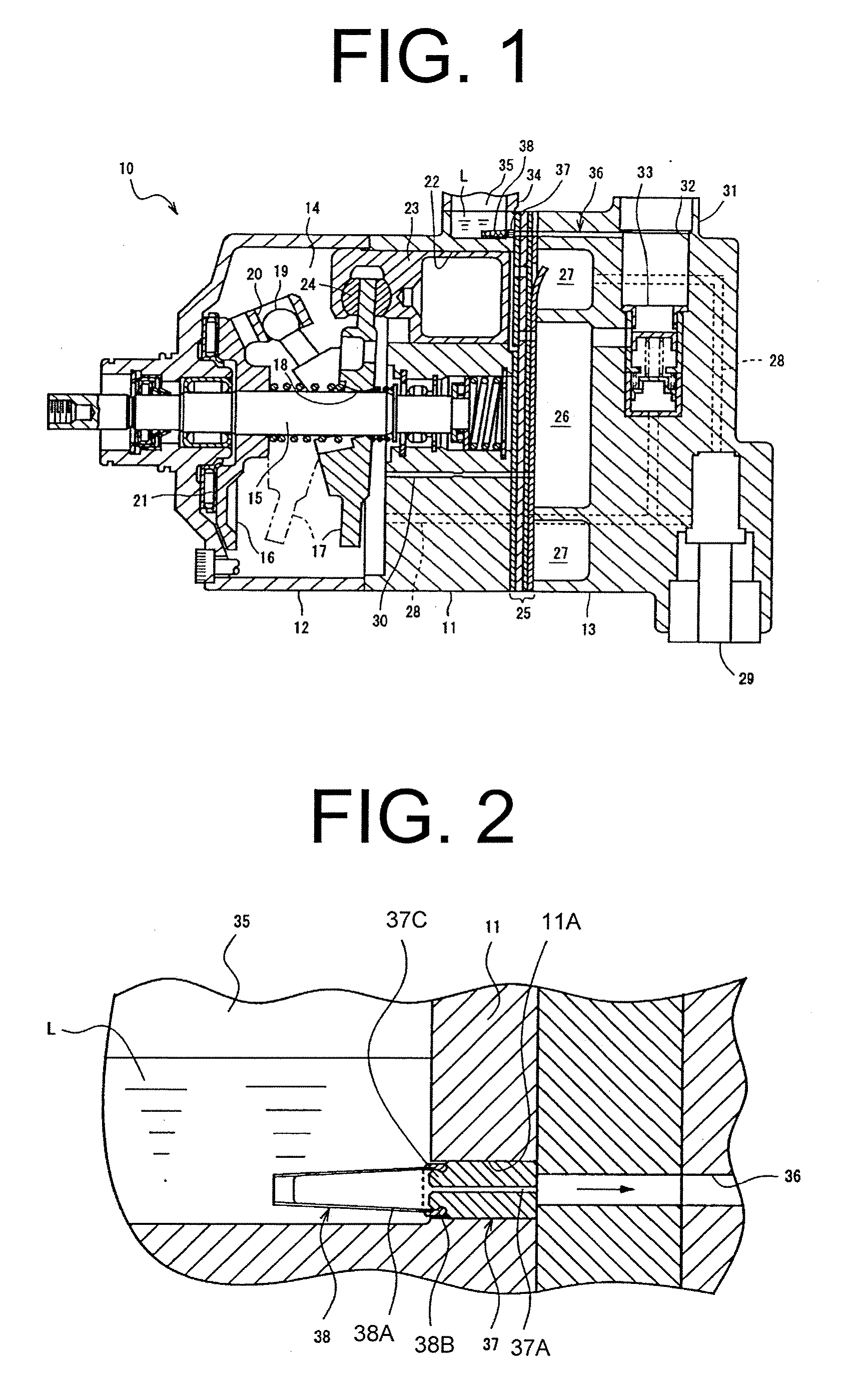
[0030]The following will describe the structure for mounting an oil filter in a variable displacement type swash plate compressor according to the present invention with reference to FIGS. 1 to 6. The variable displacement type swash plate compressor will be referred to as a compressor hereinafter. It is noted that the left-hand side and the right-hand side of the compressor 10 as viewed in FIG. 1 correspond to the front and rear of the compressor 10, respectively. As shown in FIG. 1, the compressor 10 includes a cylinder block 11, a front housing 12 joined to the front end of the cylinder block 11 and a rear housing 13 joined to the rear end of the cylinder block 11. The front housing 12, the cylinder block 11 and the rear housing 13 cooperate to form a housing that serves as an outer shell of the compressor 10. The cylinder block 11 and the front housing 12 define a crank chamber 14.

[0031]A rotary shaft 15 extends through the crank chamber 14 and is rotatably supported by the fron...

third embodiment

[0074]The structure for mounting the filter in the compressor of the third embodiment has the following advantageous effects.

(8) The recess 79A is formed on the outer circumferential surface of the valve case 79 and the projection 116 is formed on the inner circumferential surface of the side portion 113 of the filter 110. When the projection 116 is fitted into the recess 79A, the filter 110 is connected to the valve case 79. The clearance with a uniform dimension G is formed between the outer circumferential surface of the holding member 112 and the inner circumferential surface 61A of the valve receiving hole 69. This dimension G is set smaller than the overlap distance H for which the projection 116 is fitted in the recess 79A (i.e. G112 of the filter 110 is expanded radially outward, e.g. due to factors such as a thermal expansion, the fitting relation between the recess 79A and the projection 116 remains effective thereby to prevent the filter 110 from being removed from the va...

sixth embodiment

[0107]The structure for mounting the filter in the compressor has the following advantageous effects.

(12) The recess 221 is formed on the outer circumferential surface of the protrusion 219 of the cover member 217, while the projection 225 is formed on the inner circumferential surface of the holding member 224 of the filter 222. With the projection 225 fitted in the recess 221, the cover member 217 and the filter 222 are connected together. A clearance with a uniform dimension G is formed between the outer circumferential surface of the holding member 224 and the enlarged inner wall surface 201B forming part of the oil separation chamber 211. This dimension G is smaller than the overlap distance H for which the projection 225 is fitted in the recess 221 (i.e. G224 is expanded radially outward, e.g. due to factors such as a thermal expansion, therefore, the fitting relation between the recess 221 and the projection 225 remains effective thereby to prevent the filter 222 from being ...


PUM

PropertyMeasurementUnit
areaaaaaaaaaaa
overlap distanceaaaaaaaaaa
pressureaaaaaaaaaa

Abstract

In a structure for mounting a filter in a compressor, a mounting member is connected to the filter. A receiving hole is formed in a housing of the compressor for receiving therein the mounting member. A first fitting portion is formed on an inner circumferential surface of a holding portion of the filter. A second fitting portion is formed on an outer circumferential surface of the mounting member for having fitting relation to the first fitting portion for an overlap distance in a radial direction of the receiving hole. When the mounting member is received in the receiving hole with the fitting relation, the filter is disposed in a fluid passage of the housing. A clearance having a dimension is formed between an outer circumferential surface of the holding portion and an inner circumferential surface of the receiving hole. Minimum value of the dimension is smaller than the overlap distance.

Description

BACKGROUND OF THE INVENTION[0001]The present invention relates to a structure for mounting in a compressor a filter for eliminating foreign substances contained in the oil separated from refrigerant gas under a discharge pressure in the compressor.[0002]Japanese Unexamined Patent Application Publication No. 55-29040 discloses a compressor having a filter for eliminating foreign substances contained in the oil separated from refrigerant gas under a discharge pressure. The compressor of this Publication has a cylinder head having a discharge chamber therein, an oil collection chamber and an oil reservoir. An oil separator is located between the discharge chamber and the oil collection chamber. The oil reservoir is located below the oil collection chamber and communicates therewith via a communication hole. The oil reservoir also communicates with a crank chamber of the compressor via an oil return passage having a first hole, a second hole and a third hole. A capillary is inserted in ...

Claims


Application Information

Patent Timeline
Patent Type & Authority Applications(United States)
IPC IPC(8): F04B53/20B01D35/30
CPCF04B27/1081F04B39/16F04B27/109F04B27/0878F04B27/1018F04B27/1045F05B2210/12F05B2210/14F05B2260/63Y10S417/00
Inventor INOUE, YOSHINORINAKAIMA, HIROYUKITAKASHIMA, YOICHISHINMYO, KAZUYASAKAGAMI, ATSUOSAKAMOTO, MASAYAUMEMURA, SATOSHIKOEDA, NAOKIHASHIMOTO, YUJIKONDO, HISAYA
Owner TOYOTA IND CORP
Features
  • R&D
  • Intellectual Property
  • Life Sciences
  • Materials
  • Tech Scout
  • Unparalleled Data Quality
  • Higher Quality Content
  • 60% Fewer Hallucinations
Learn More