Vehicle drive unit

a technology of drive unit and drive shaft, which is applied in the direction of friction gearing, gearing elements, gearing, etc., can solve the problems of blocking the oil flow toward the hydraulic control valve, and achieve the effect of reliably preventing belt slippage, short time, and efficient supply of hydraulic pressur

Inactive Publication Date: 2009-06-04
AISIN AW CO LTD
View PDF12 Cites 20 Cited by
  • Summary
  • Abstract
  • Description
  • Claims
  • Application Information

AI Technical Summary

Benefits of technology

[0032]When driving of the oil pump is started, almost no hydraulic pressure is required to be applied to the primary pulley, while the hydraulic pressure needs to be applied to the secondary pulley. By providing the one-way valve on the secondary pulley side, oil leakage from the secondary pulley is suppressed, whereby slippage of the belt can be reliably prevented.
[0033]As described above, the vehicle drive unit according to the present invention is capable of efficiently supplying a hydraulic pressure from an accumulator to a hydraulic servo in a short time while minimizing the capacity of the accumulator.

Problems solved by technology

However, the oil flow toward the hydraulic control valve is blocked by the first one-way valve.

Method used


Image

  • Vehicle drive unit
  • Vehicle drive unit
  • Vehicle drive unit

Examples


first non-limiting embodiment

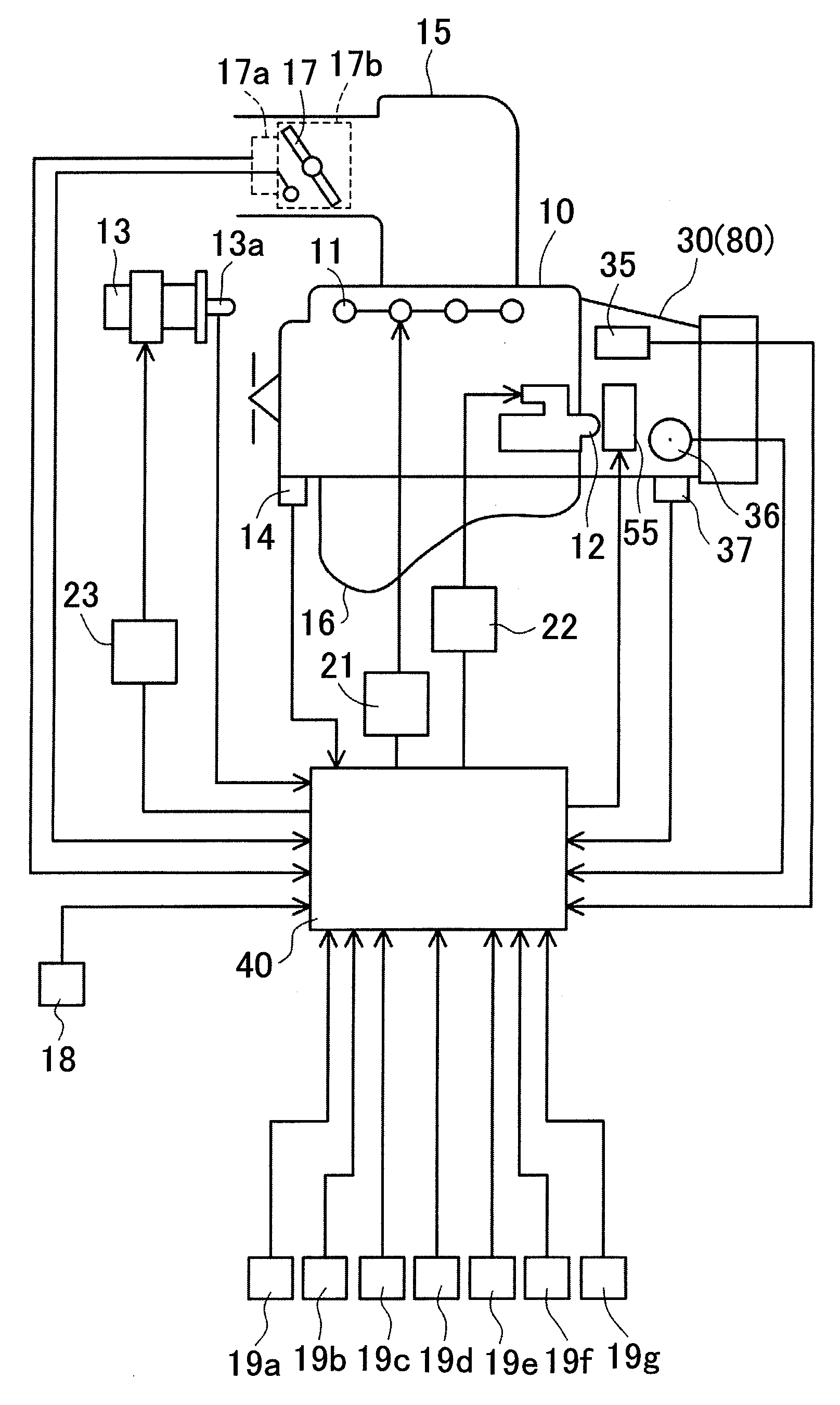
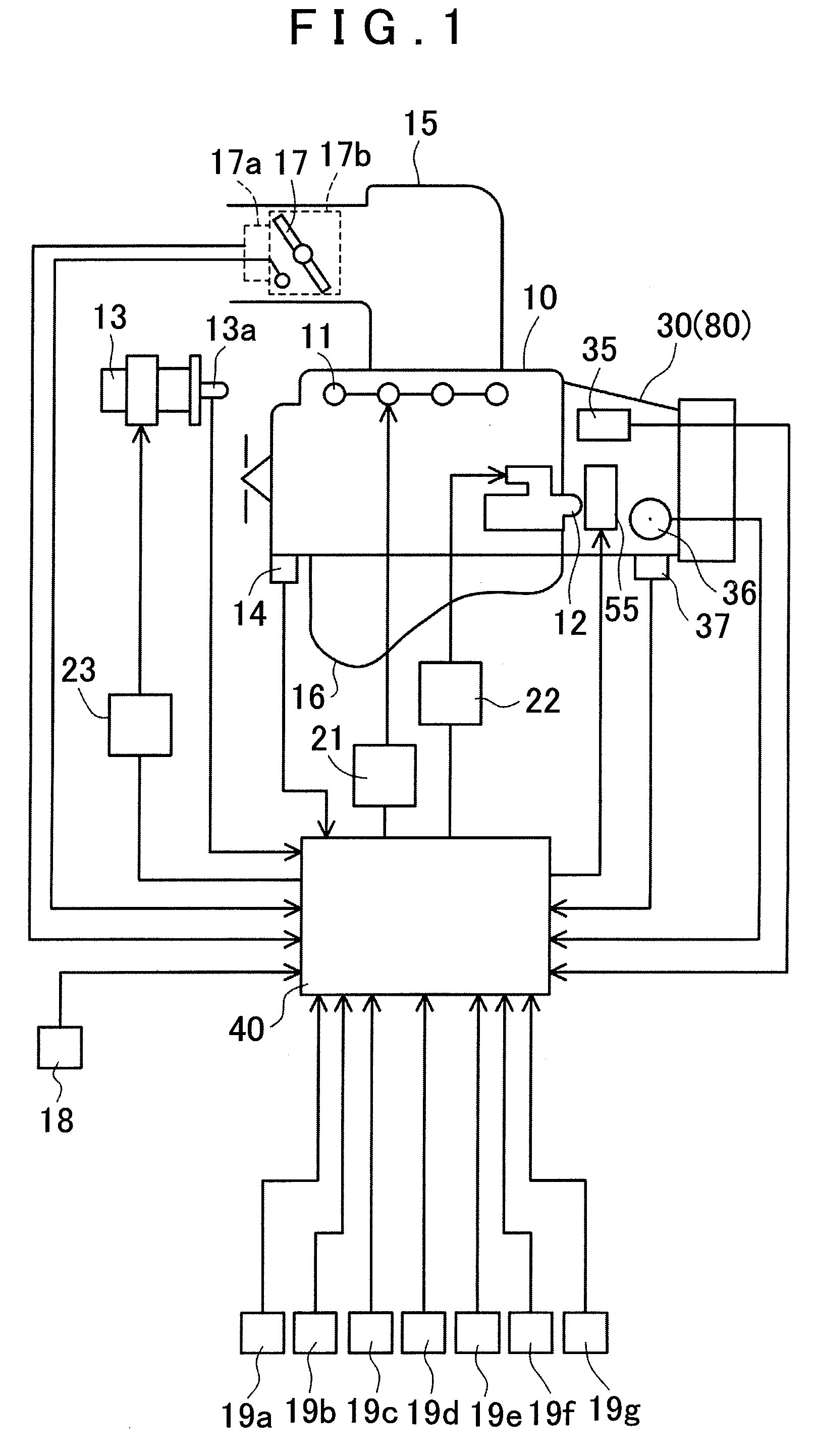
[0042]First, a first non-limiting embodiment will be described. In the first embodiment, the present invention is applied to a vehicle drive system having a continuously variable transmission (CVT). The vehicle drive system of the first embodiment will now be described with reference to FIG. 1. FIG. 1 is a structural diagram schematically showing a structure of the vehicle drive system according to the first embodiment.

[0043]As shown in FIG. 1, the drive system of the first embodiment includes an engine 10, a continuously variable transmission 30, a control unit 40 that provides overall control over the system, and various sensors for detecting, for example, the states of the engine 10, the continuously variable transmission 30 and a vehicle.

[0044]An injector 11, a starter 12, and an igniter 13 are provided in the engine 10. The continuously variable transmission 30 is connected to an output shaft of the engine 10.

[0045]An intake manifold 15 and an exhaust manifold 16 are connected ...

second non-limiting embodiment

[0084]Hereinafter, a second non-limiting embodiment will be described. The second embodiment has substantially the same basic structure as that of the first embodiment, but is different from the first embodiment in the structure of the hydraulic circuit included in the continuously variable transmission. In the following description, the same structural elements as those of the first embodiment are denoted by the same reference numerals and characters, and description thereof will be omitted as appropriate. The hydraulic circuit of the vehicle drive system of the second embodiment will be described mainly regarding the differences in structure from the first embodiment with reference to FIG. 5. FIG. 5 is a diagram showing a hydraulic circuit in the vehicle drive system of the second embodiment.

[0085]As shown in FIG. 5, in a hydraulic circuit 50a, the oil passage 63 to which the accumulator 56 is connected is connected to an oil passage 65a that connects the manual valve 54 and the f...

third non-limiting embodiment

[0089]Finally, a third non-limiting embodiment will be described. Unlike the first and second embodiments, the present invention is applied to a stepped automatic transmission (stepped AT) in the third embodiment. The basic structure of the third embodiment is substantially the same as that of the second embodiment. However, the continuously variable transmission 30 is replaced with a stepped automatic transmission 80 (see FIG. 1), and the structure of a hydraulic circuit provided in the stepped automatic transmission 80 is different from that of the second embodiment. In the following description, the same structural elements as those of the second embodiment are denoted by the same reference numerals and characters, and description thereof will be omitted as appropriate. The hydraulic circuit in the vehicle drive system of the third embodiment will be described mainly regarding the differences in structure from the second embodiment with reference to FIG. 6. FIG. 6 is a diagram sh...


PUM


Abstract

A vehicle drive unit is provided which includes a hydraulic circuit capable of efficiently supplying a hydraulic pressure from an accumulator to a hydraulic servo while minimizing the capacity of the accumulator. In a hydraulic circuit included in a continuously variable transmission, an accumulator is connected through an electromagnetic switch valve to an oil passage connecting a clutch pressure control valve and a manual valve, a one-way valve for allowing oil to flow only in the direction from the clutch pressure control valve toward the accumulator and the forward clutch is provided in the oil passage. The electromagnetic switch valve switches an oil passage to a communicating state when the oil pump is driven and switches the oil passage to a shut-off state when the oil pump is stopped.

Description

INCORPORATION BY REFERENCE[0001]The disclosure of Japanese Patent Application No. 2007-310765 filed Nov. 30, 2007 including the specification, drawings and abstract is incorporated herein by reference in its entirety.BACKGROUND OF THE INVENTION[0002]1. Field of the Invention[0003]The present invention relates to a vehicle drive unit that quickly supplies a hydraulic pressure to a hydraulic servo upon restarting of an engine to enable, for example, rapid engagement of a friction engagement element that enables starting of a vehicle.[0004]2. Description of the Related Art[0005]In known art, a vehicle having a function to automatically stop an engine when predetermined conditions are satisfied during running of the vehicle (an idling stop function) has been put to practical use in order to achieve fuel saving, reduction in exhaust gas emission, noise reduction, and the like. In such a vehicle, the engine is stopped when all of conditions such as zero vehicle speed, accelerator OFF, and...

Claims


Application Information

Patent Timeline
Patent Type & Authority Applications(United States)
IPC IPC(8): B60W10/10F16H61/28F16H59/08F16H61/00F16H61/66F16H61/662
CPCF16H61/0021F16H61/66272F16H2061/0034Y10T477/6243F16H2312/14Y10T477/693742Y10T477/6425F16H2061/66286
Inventor OHSHIMA, ATSUYATSUZUKI, SHIGEOYAMASHITA, MITSUGISHIRASAKA, HARUKI
Owner AISIN AW CO LTD
Why Eureka
Try Eureka