Method for Determining Contact Erosion of an Electromagnetic Switching Device, and Electromagnetic Switching Device Comprising a Mechanism Operating According to Said Method

a technology of electromagnetic switching and contact erosion, which is applied in the direction of circuit-breaking switches, distance measurement, instruments, etc., can solve the problems of contact erosion and the inability to determine the time at which the contacts close, and achieve the effect of precise determination of contact erosion

Inactive Publication Date: 2009-06-04
SIEMENS AG
View PDF2 Cites 18 Cited by
  • Summary
  • Abstract
  • Description
  • Claims
  • Application Information

AI Technical Summary

Benefits of technology

[0008]One potential object is to specify a method for determining the erosion of contacts of an electromagnetic switching device, with which method precise determination of the time at which the contacts close an

Problems solved by technology

These arcs cause erosion of the contacts over the course of time.
In practice, however, it has been established that

Method used


Image

  • Method for Determining Contact Erosion of an Electromagnetic Switching Device, and Electromagnetic Switching Device Comprising a Mechanism Operating According to Said Method
  • Method for Determining Contact Erosion of an Electromagnetic Switching Device, and Electromagnetic Switching Device Comprising a Mechanism Operating According to Said Method
  • Method for Determining Contact Erosion of an Electromagnetic Switching Device, and Electromagnetic Switching Device Comprising a Mechanism Operating According to Said Method

Examples


Embodiment Construction

[0022]Reference will now be made in detail to the preferred embodiments of the present invention, examples of which are illustrated in the accompanying drawings, wherein like reference numerals refer to like elements throughout.

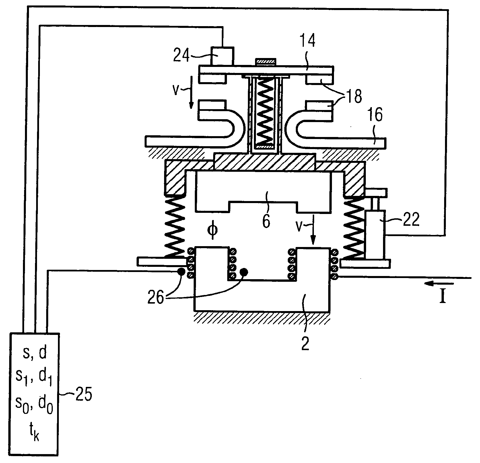
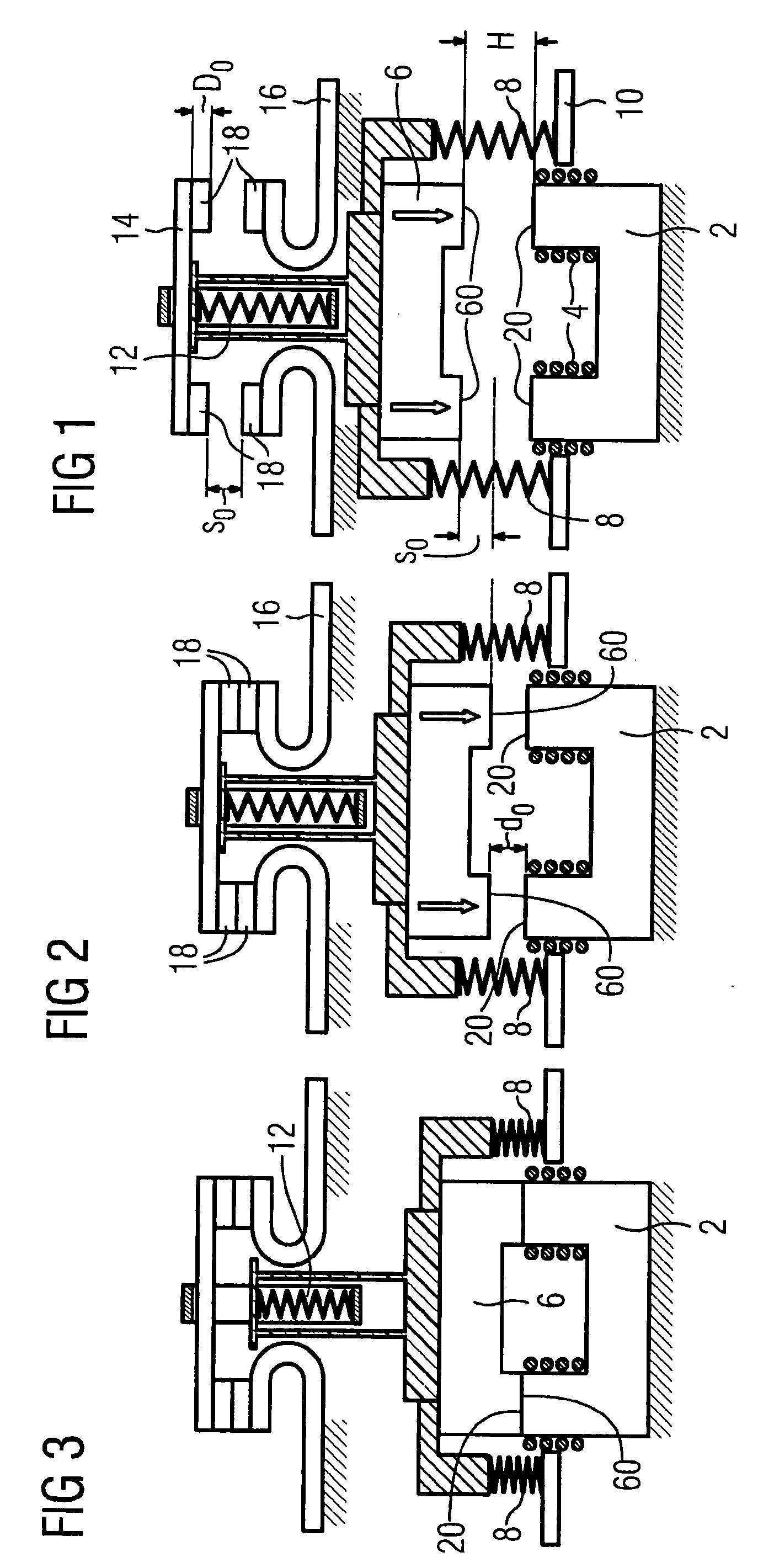
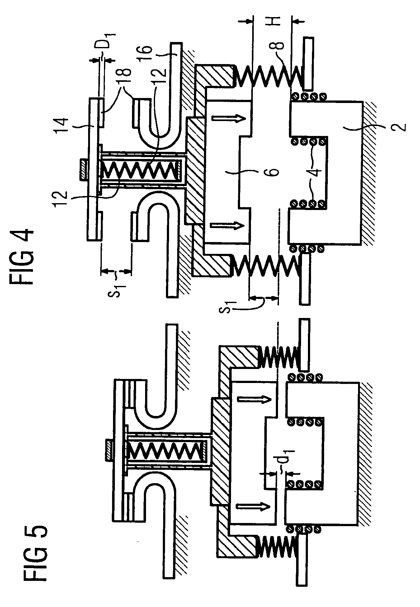
[0023]As shown in FIG. 1, an electromagnetic switching device, in the example illustrated a contactor, contains a magnet yoke 2, on which two magnet coils 4 are arranged for magnetic excitation purposes. A magnet armature 6, which is associated with the magnet yoke 2, is mounted in a sprung manner by compression springs 8 in a housing 10 (which is only illustrated symbolically) of the switching device. The magnet yoke 2, magnet coil 4 and magnet armature 6 form an electromagnetic drive of the switching device. The magnet armature 6 is connected in a force-fitting manner to a moveable contact link 14 via a contact spring 12. Two stationary contact carriers 16 are associated with the moveable contact link 14. The magnet armature 6 forms the actuator of the magn...


PUM


Abstract

In order to determine contact erosion of an electromagnetic switching device, a mechanical parameter is measured which characterizes the time course of the relative movement between the contacts, said movement being caused by an actuator. The point in time when the contacts close is determined by evaluating the time course of the relative movement, and the distance traveled by the contacts until said point in time or the distance traveled by the actuator from said point in time until reaching the final position thereof is detected at least indirectly and is compared to a stored reference value.

Description

CROSS REFERENCE TO RELATED APPLICATIONS[0001]This application is based on and hereby claims priority to German Application No. 10 2005 045 095.4 filed on Sep. 21, 2005 and PCT Application No. PCT / EP2006 / 066166 filed on Sep. 8, 2006, the contents of which are hereby incorporated by reference.BACKGROUND OF THE INVENTION[0002]The invention relates to a method for determining the erosion of contacts of an electromagnetic switching device. In addition, the invention relates to an electromagnetic switching device with a device for determining the erosion of its contacts.[0003]During the switch-on and switch-off operations of an electromagnetic switching device, arcs occur between the closing or opening contacts. These arcs cause erosion of the contacts over the course of time. It is therefore important for the operational reliability of such a switching device to identify the degree of this erosion in order to be able to draw conclusions on the residual life of the switching device and av...

Claims


Application Information

Patent Timeline
IPC IPC(8): G01B21/02
CPCH01H1/0015H01H2071/044H01H73/045H01H50/546H01H1/00
Inventor ELSNER, NORBERTMITLMEIER, NORBERTTRAUTMANN, BERND
Owner SIEMENS AG
Why Eureka
Try Eureka