Single mass dual mode crankshaft damper with tuned hub

a crankshaft damper and hub technology, applied in the field of dampers, can solve the problems of many modes of unwanted vibration, many automotive vehicles suffer from unwanted noise, vibration, harshness, etc., and achieve the effect of reducing torsional vibration and bending vibration, and cost-effectively reducing other undesirable engine noises

Inactive Publication Date: 2009-06-11
METALDYNE LLC
View PDF15 Cites 22 Cited by
  • Summary
  • Abstract
  • Description
  • Claims
  • Application Information

AI Technical Summary

Benefits of technology

[0011]It is an object of the present invention to provide a cost effective damper to reduce torsional vibrations and bending vibrations as well as other undesirable engine noises.
[0012]It is another object of the present invention to provide a single mass dual mode damper capable of separate and individual tuning of torsional vibration, bending vibration, and / or an additional axial set of vibrations without interference or magnification.
[0013]It is still another object of the present invention to provide a dual mode damper which can be assembled with existing tooling and use of existing techniques.

Problems solved by technology

However, the rotation and torque on the crankshaft causes many modes of unwanted vibrations.
Additionally, many automotive vehicles suffer from unwanted noise, vibration, and harshness (“NVH”) resulting from other modes of engine vibrations.
Unless controlled, torsional vibrations, bending vibrations, and other NVH leads to failure of the crankshaft and contributes to the failure of other engine parts.
Torsional dampers of this type are capable of reducing torsional vibrations, however are limited in overcoming axial shifting and bending vibrations.
Additionally, conventional torsional dampers fail to cure NVH and reduce the resonance and magnification of NVH frequently occurring within the engine.
Although this design addresses torsional and bending vibrations, the additional inertia member and elastomer member add unwanted weight and increase production costs of the damper.
In addition, the dampener fails to cure the problems of NVH within the engine.
While this design addresses torsional and bending vibrations, it is limited in preventing NVH and also can result in magnification of NVH, such as when the NVH vibrations overlay into the same frequency range as the damper hub.
The problem can be exacerbated when peak resonance points of the damper hub are aligned and in phase with resonance points of the crankshaft and engine.

Method used


Image

  • Single mass dual mode crankshaft damper with tuned hub
  • Single mass dual mode crankshaft damper with tuned hub
  • Single mass dual mode crankshaft damper with tuned hub

Examples


Embodiment Construction

[0018]While the present invention is described with reference to the embodiments described herein, it should be clear that the present invention should not be limited to such embodiments. Therefore, the description of the embodiments herein is illustrative of the present invention and should not limit the scope of the invention as claimed.

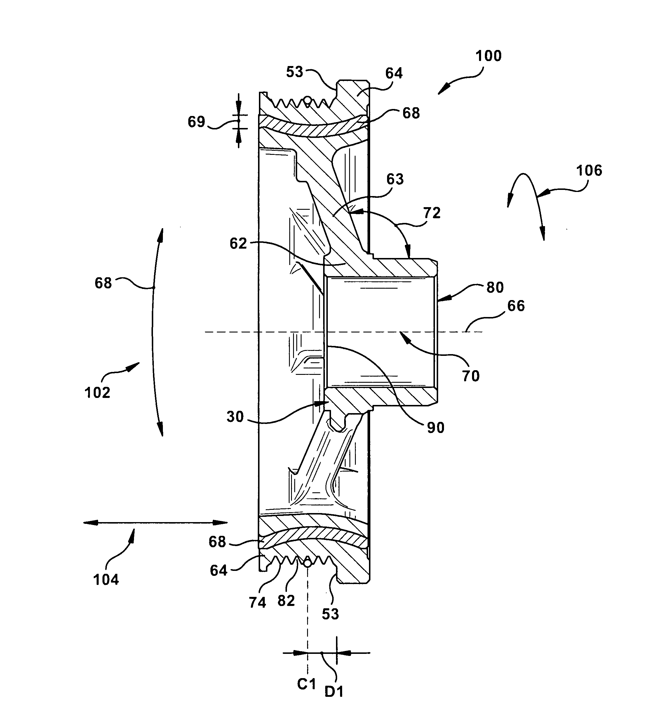
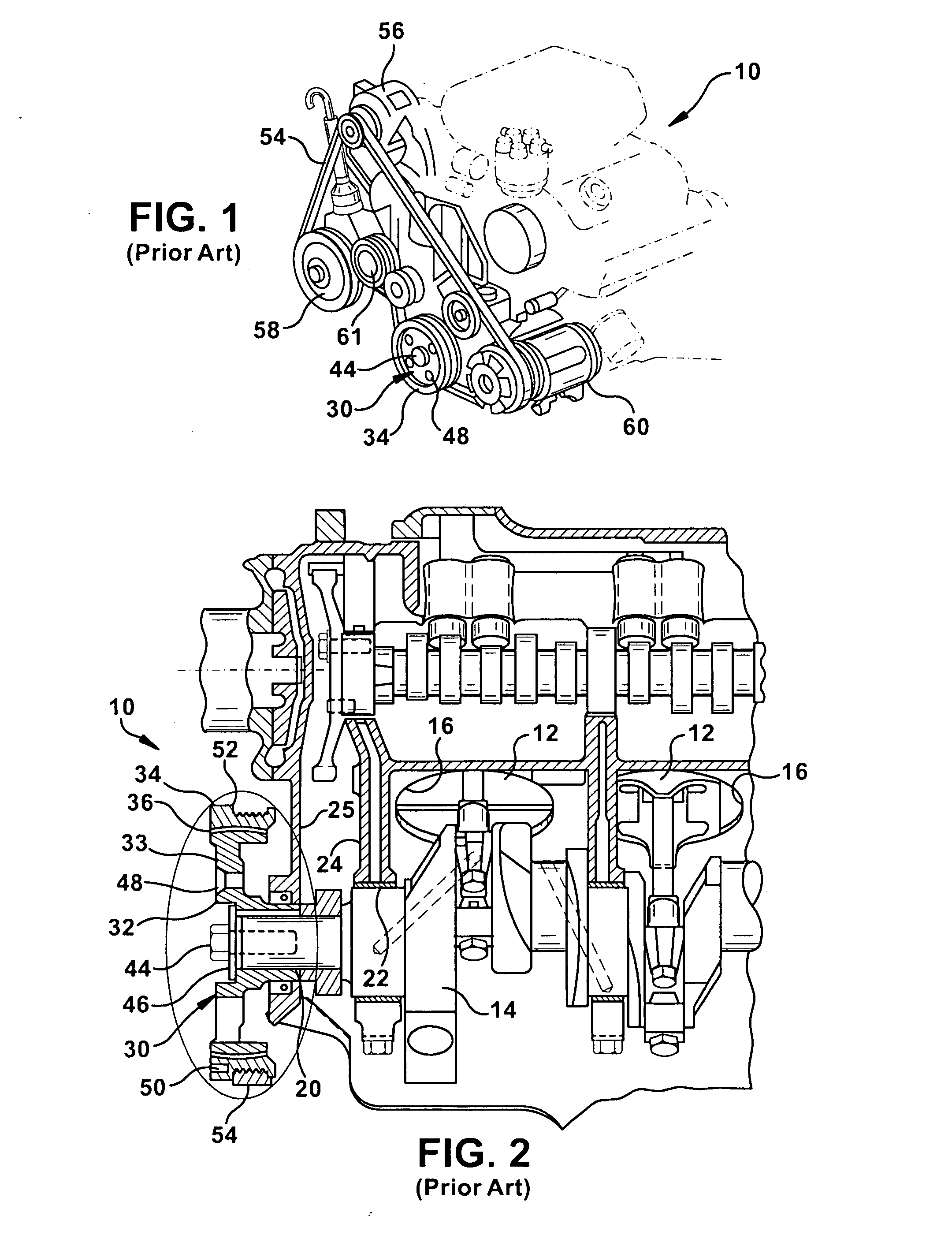
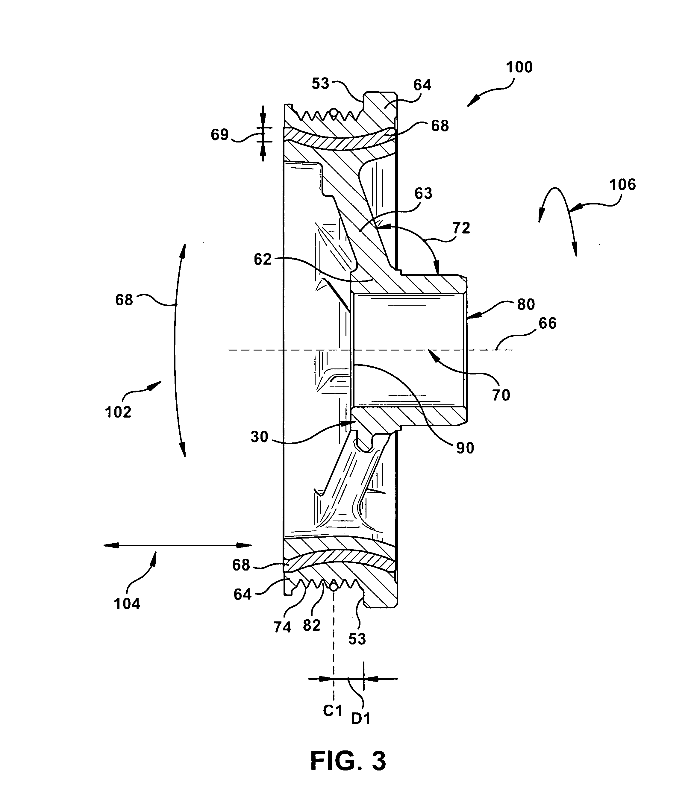
[0019]As illustrated in FIG. 3, a damper 100 is provided for dampening vibrations within an engine, such as the engine 10 of FIGS. 1 and 2. The damper 100 may have an opening 80 for attachment to a crankshaft, such as the crankshaft 14 of FIGS. 1 and 2, or other engine component. The damper 100 consists of an inertia member 64, a hub member 62, and a elastomer 68. The inertia member 64 may be spaced radially outward from the hub member 62. The elastomer 68 may be positioned between the hub member 62 and the inertia member 64. In an embodiment, the elastomer 68 is positioned under compression between the hub member 62 and the inertia member 64.

[0020...


PUM


Abstract

A damper for attachment to a crankshaft of an engine is provided. The damper has a hub member, an inertia member spaced radially outward from the hub member and an elastomer positioned between the hub member and the inertia member. The hub member has an opening for attachment to the crankshaft and extends at an angle away from the opening such that the inertia member is offset from the opening of the hub member. The offset inertia member prevents amplification of noise from the crankshaft. The elastomer has a curvature to improve dampening of bending vibrations.

Description

CROSS-REFERENCE TO RELATED APPLICATIONS[0001]This application claims priority from U.S. Provisional Patent Application No. 60 / 922,822 entitled “SINGLE MASS DUAL MODE CRANKSHAFT DAMPER WITH TUNED HUB,” filed on Apr. 11, 2007, which is hereby incorporated by reference in its entirety.FIELD OF THE INVENTION[0002]The present invention relates generally to a damper, and more particularly to a damper that reduces vibrations and noise of an internal combustion engine.BACKGROUND OF THE INVENTION[0003]As is well known in the art, internal combustion engines are used to drive automobiles and other vehicles. Typically, the reciprocating operation of the cylinders in an internal combustion engine generates power that is transmitted to wheels of the vehicle through a crankshaft. The engine has a cylinder head consisting of numerous cylinders where a sequential explosion of gases in the cylinders drives the crank shaft. One end of the crankshaft may be used to drive the wheels, and the other end ...

Claims


Application Information

Patent Timeline
Patent Type & Authority Applications(United States)
IPC IPC(8): F16F15/12
CPCF16F15/126F16H55/36Y10T74/2131F16H2055/366F16H2055/363F16F2226/042F16F15/1442
Inventor OBESHAW, RICHARD
Owner METALDYNE LLC
Why Eureka
Try Eureka